
Liquid crystal display apparatus

a technology of liquid crystal display and display device, which is applied in the direction of printed circuit details, instruments, printed circuits, etc., can solve the problems of components being damaged, components being damaged, and liquid crystal display apparatus being difficult to assemble, so as to minimize a number of defects, improve durability, and minimize distance

Active Publication Date: 2016-01-28
LG DISPLAY CO LTD
View PDF5 Cites 30 Cited by
  • Summary
  • Abstract
  • Description
  • Claims
  • Application Information

AI Technical Summary

Benefits of technology

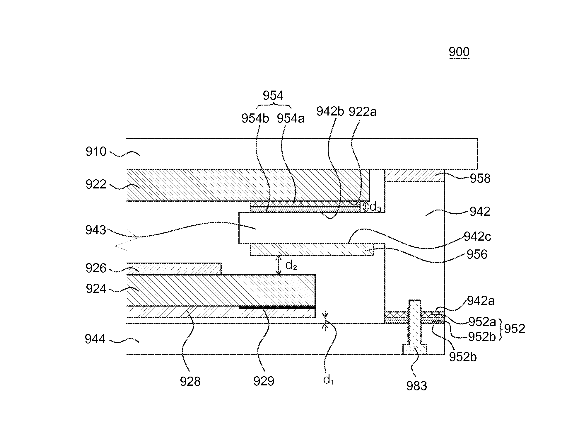
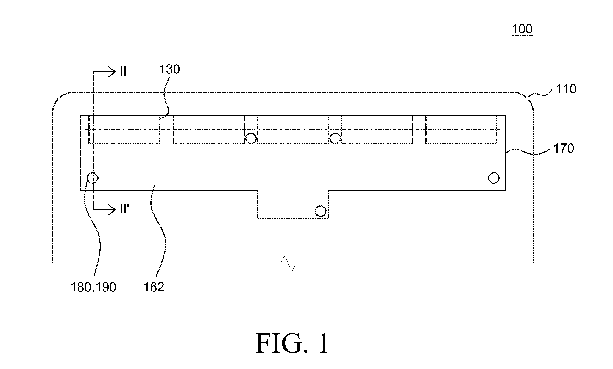
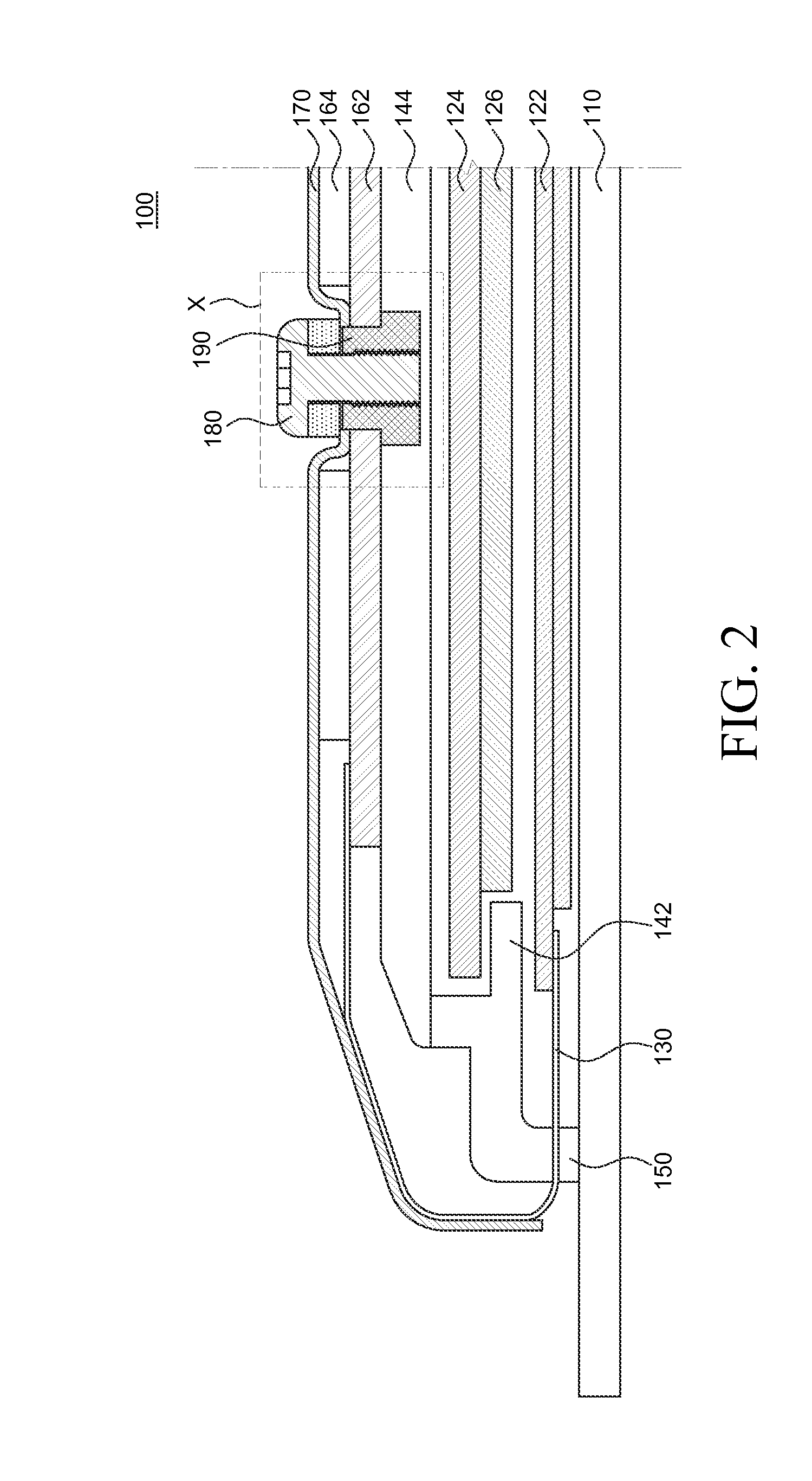
The present invention aims to provide a liquid crystal display apparatus that can minimize defects by efficiently fixing components. Additionally, the invention includes a pad structure to reduce interference and light leakage from a backlight.

Problems solved by technology

If the components are not accurately fixed at positions as designed and thus a minimum distance therebetween cannot be secured, the components may be brought into undesired contact with each other or another component may be located at a position of one component, so that the liquid crystal display apparatus may be difficult to assemble.
However, a pressure applied to the liquid crystal display apparatus when the fixing structure is connected with the liquid crystal display apparatus may cause a change in a distance between the components of the liquid crystal display apparatus, and, thus, the components may be damaged.
In addition, if a force is applied to the fixing structure in order to fix the shield unit, the components apply a pressure to each other, thereby causing damage to the components and various problems may occur.
If alignment of the liquid crystal is changed, a light-leakage phenomenon may occur in the liquid crystal display panel, resulting in a decrease in visibility.
However, in recent years, there is a tendency not to use the cover unit in order to further reduce thickness of the liquid crystal display apparatus.
However, if a pad unit formed of silicon is used in a structure without using the cover unit, a pressure is applied to the liquid crystal display panel, and, thus, light leakage caused by a change in alignment of the liquid crystal may be directly exposed to a user.

Method used


Image

  • Liquid crystal display apparatus
  • Liquid crystal display apparatus
  • Liquid crystal display apparatus

Examples


Embodiment Construction

[0059]Advantages and features of the present disclosure, and methods for accomplishing the same will be more clearly understood from exemplary embodiments described below with reference to the accompanying drawings. However, the present disclosure is not limited to the following exemplary embodiments but may be implemented in various different forms. The exemplary embodiments are provided only to complete disclosure of the present disclosure and to fully provide a person having ordinary skill in the art to which the present disclosure pertains with the category of the disclosure, and the present disclosure will be defined by the appended claims.

[0060]The shapes, sizes, ratios, angles, numbers, and the like illustrated in the accompanying drawings for describing the exemplary embodiments of the present disclosure are merely examples, and the present disclosure is not limited thereto. Like reference numerals generally denote like elements throughout the present specification. Further,...


PUM

PropertyMeasurementUnit
thicknessaaaaaaaaaa
thicknessaaaaaaaaaa
flexibleaaaaaaaaaa

Abstract

Provided is a liquid crystal display apparatus according to an exemplary embodiment of the present disclosure. The liquid crystal display apparatus includes: a liquid crystal display panel; a first chassis; a second chassis; a circuit unit; a flexible substrate; a shield unit; and a pem-nut. The shield unit is disposed to surround at least a part of the flexible substrate and circuit unit and be bonded to at least a part of the flexible substrate. The pem-nut is exposed through a hole penetrating the shield unit and the circuit unit, and a bolt-insertion part is disposed. A top side of the pem-nut is positioned to be higher than a top side of the circuit unit. In the liquid crystal display apparatus according to an exemplary embodiment of the present disclosure, the reliability of the liquid crystal display apparatus is improved.

Description

CROSS-REFERENCE TO RELATED APPLICATIONS[0001]This application claims the priority of Korean Patent Application No. 10-2014-0094959 filed on Jul. 25, 2014, and Korean Patent Application No. 10-2014-0119549 filed on Sep. 7, 2014, in the Korean Intellectual Property Office, the disclosures of which are hereby incorporated herein by reference.BACKGROUND[0002]1. Field of the Invention[0003]The present disclosure relates to a liquid crystal display apparatus, and more particularly, to a liquid crystal display apparatus which is capable of reducing assembly defects of the liquid crystal display apparatus by improving a bolting structure for assembling components, and realizing a thinner liquid crystal display apparatus. Also, by applying a pad unit composed of a foam pad layer and a rigid layer, a distance between the components can be secured and an impact of collision between the components can be relieved.[0004]2. Description of the Related Art[0005]A liquid crystal display apparatus is...

Claims


Application Information

Patent Timeline
Patent Type & Authority Applications(United States)
IPC IPC(8): G02F1/1333G02F1/1335H05K1/02
CPCG02F1/133308G02F1/133524H05K2201/10136H05K1/028G02F2001/133317G02F1/133553G02F1/133322G02F1/133325G02F1/13452G02F2201/46G02F1/133314
Inventor KANG, CHANGGONGHER, HYUNGGUKIM, TAEMIN
Owner LG DISPLAY CO LTD
Learn More