

Drift-corrected, high-resolution optical trap and high-sensitivity angular interferometer
- Summary
- Abstract
- Description
- Claims
- Application Information
AI Technical Summary
Benefits of technology
Problems solved by technology
Method used
Image

Examples
Embodiment Construction
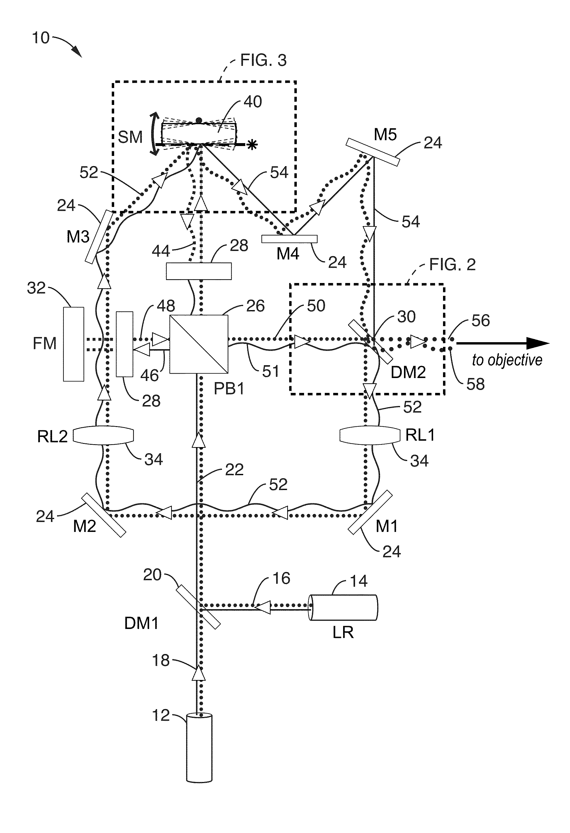
[0030]The systems and methods of the present invention may be implemented within a number of different types of optical instruments wherein correction for mechanical drift in optical components of the instruments is desired. Two such implementations are detailed below with respect to optical traps and interferometers. However, one skilled in the art would appreciate that the systems and methods of the present invention may be applied to any number of optical systems.
[0031]A. Drift-Corrected, High-Resolution Optical Trap.
[0032]The optical traps, or tweezers, of the present invention employ two reference beams with an optical property that allows them to be separated from the two trapping beams, for instance with a different wavelength. The reference and trapping beams are combined collinearly, and there each reference beam travels the same path as one of the trapping beams and thus experience the same angular noise. Before being sent to the microscope objective, the reference beams a...
PUM
 Abstract
Description
Claims
Application Information