Base station

a base station and station technology, applied in the field of base stations, can solve the problems of reducing the delay amount, and achieve the effect of high accuracy

Active Publication Date: 2016-01-28
PANASONIC CORP
View PDF3 Cites 26 Cited by
  • Summary
  • Abstract
  • Description
  • Claims
  • Application Information

AI Technical Summary

Benefits of technology

[0011]According to the present invention, sensing of a frequency can be performed with high accuracy with a transmission rate almost identical to the conventional transmission rate, even when the distance between a terminal and a base station is short.

Problems solved by technology

The amount of delay decreases as the distance between the mobile station and the base station decreases.

Method used


Image

  • Base station
  • Base station
  • Base station

Examples


embodiment 1

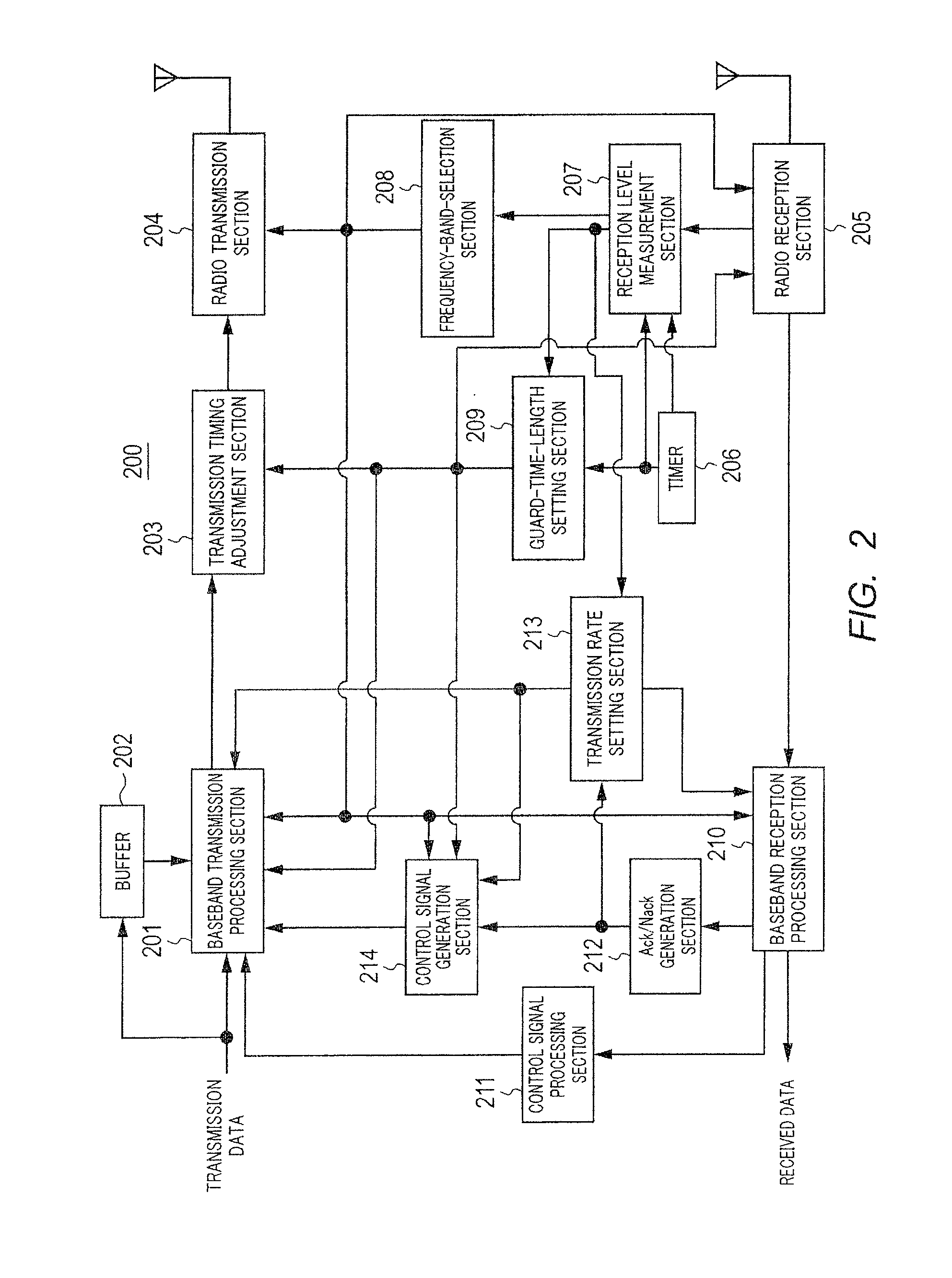
[0031]A radio communication system according to Embodiment 1 includes terminal 100 illustrated in FIG. 1 and base station 200 illustrated in FIG. 2. Terminal 100 and base station 200 are each an FPU used in transmission of materials in a broadcasting sector, for example. More specifically, terminal 100 transmits video information or the like to base station 200 as a UL signal, and base station 200 transmits feedback information or the like to terminal 100 as a DL signal.

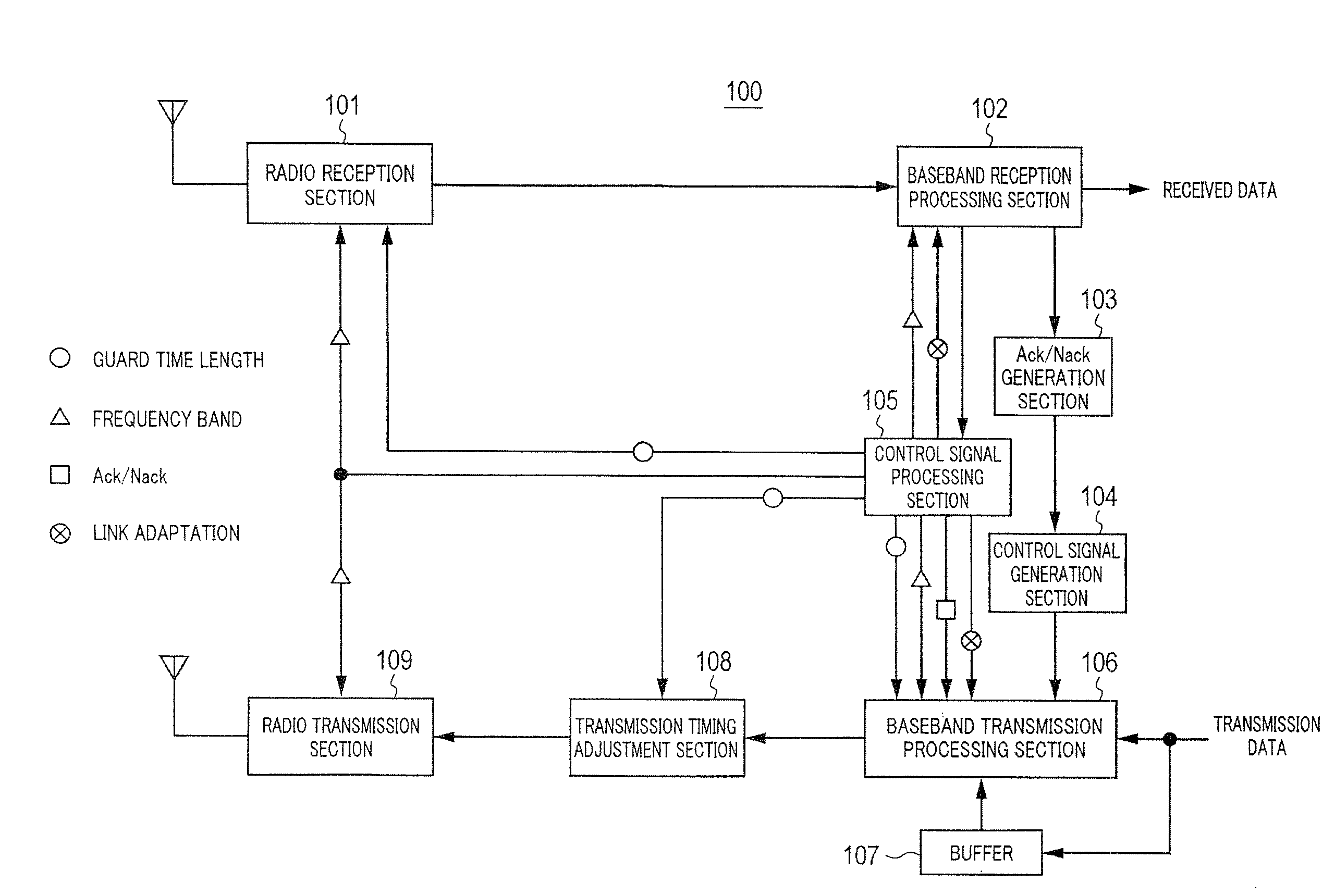
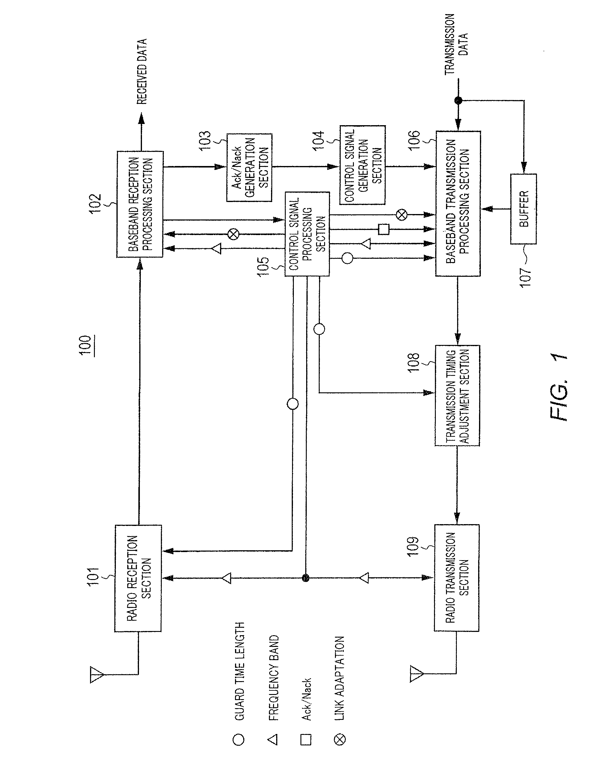
[0032]To begin with, a description will be given of a configuration example of terminal 100 according to Embodiment 1 with reference to FIG. 1. FIG. 1 is a block diagram illustrating a configuration example of terminal 100 according to Embodiment 1.

[0033]In FIG. 1, terminal 100 mainly includes radio reception section 101, baseband reception processing section 102, Ack / Nack generation section 103, control signal generation section 104, control signal processing section 105, baseband transmission processing section 106...

embodiment 2

[0084]A description will be given of Embodiment 2. The configuration of terminal 100 according to Embodiment 2 is the same as the configuration described in FIG. 1, which is described in Embodiment 1, so that the same description will not be repeated, hereinafter.

[0085]A description will be given of a configuration example of base station 200A according to Embodiment 2 with reference to FIG. 6. FIG. 6 is a block diagram illustrating the configuration example of base station 200A according to Embodiment 2. Each section of base station 200A illustrated in FIG. 6 is assigned the same reference numeral assigned to the corresponding section of base station 200 illustrated in FIG. 2. Hereinafter, a description will be given of only a configuration element that performs an operation different from the operations in FIG. 2, among the sections illustrated in FIG. 6.

[0086]A predetermined first period of time (e.g., 10 ms) and a predetermined second period of time (e.g., 10 s) are set for time...

embodiment 3

[0105]In Embodiment 1, a description has been given of the case where guard-time-length setting section 209 sets the second length (predetermined length required for measurement of a reception level) for the length of a guard time always at the interval of the second periods of time.

[0106]In Embodiment 3, a description will be given of a case where the communication quality is estimated in advance, and only when the communication quality deteriorates, guard-time-length setting section 209 sets a second length for the length of the guard time at the dining when the second period of time passes. Note that, the configuration of terminal 100 according to Embodiment 3 is the same as the configuration illustrated in FIG. 1, which is described in Embodiment 1, so that the description of the configuration will not be repeated, hereinafter.

[0107]A description will be given of a configuration example of base station 200B according to Embodiment 3 with reference to FIG. 11. FIG. 11 is a block ...


PUM


Abstract

The present invention aims to perform sensing of a frequency with high accuracy by securing a sufficient amount of time to measure a reception level of a guard time while avoiding a decrease in transmission rate as much as possible even when the distance between a terminal and a base station is short. To this end, a base station is disclosed which is configured to set a guard time based on the measured reception level of a UL signal during a period other than a period when it is time to measure an interference amount. Meanwhile, the base station sets a guard time so as to secure a predetermined length required for measurement of a reception level when it is time to measure the interference amount.

Description

CROSS REFERENCE TO RELATED APPLICATION[0001]This application is entitled to and claims the benefit of Japanese Patent Applications No. 2014-153012, filed on Jul. 28, 2014, and No. 2015-012250, filed on Jan. 26, 2015, the disclosures of which including the specifications, drawings and abstracts are incorporated herein by reference in their entireties.TECHNICAL FIELD[0002]The present invention relates to a base station configured to perform radio communication with a terminal.BACKGROUND ART[0003]Field pickup units (FPUs) are known as apparatuses used in a radio communication system for video transmission such as live television broadcasting or emergency broadcasting. Such an FPU is used for transmitting materials of a broadcasting sector and configured to transmit an uplink (UL) signal of the main content information from of a scene-reporting-side mobile station (terminal) to a broadcast-station-side base station, while transmitting a downlink (DL) signal of feedback information from ...

Claims


Application Information

Patent Timeline
Patent Type & Authority Applications(United States)
IPC IPC(8): H04W24/08H04L12/26
CPCH04W24/08H04W88/08H04L43/50H04L5/0055H04L27/2646H04W24/02
Inventor SUDO, HIROAKI
Owner PANASONIC CORP
Why Eureka
Try Eureka