Method and system for controllably administering fluid to a patient and/or for controllably withdrawing fluid from the patient

a technology for controlling the flow of fluid to the patient and the control of the flow to the patient, which is applied in the direction of automatic syringes, infusion syringes, other medical devices, etc., and can solve the problems of nerve damage, ineffective anesthesia, and significant nerve damag

Active Publication Date: 2016-02-04
MEDOVATE LTD
View PDF16 Cites 19 Cited by
  • Summary
  • Abstract
  • Description
  • Claims
  • Application Information

AI Technical Summary

Benefits of technology

[0014]According to still another aspect of the invention, there is provided a method for controllably administering fluid to a patient and/or for controllably withdrawing fluid from the patient, the method comprising (a) providing the above-described system; (b) positioning the infusion needle at a desired loc

Problems solved by technology

If the needle tip is more than 5 mm from the nerve, the anesthesia may be ineffective.
If the needle tip touches the nerve, such contact of the nerve by the needle tip may cause nerve damage.
In addition, despise the advent of techniques to help position the needle correctly, the needle tip may inadvertently be inserted into a nerve.
As can be appreciated, if insertion of the needle tip into a nerv

Method used


Image

  • Method and system for controllably administering fluid to a patient and/or for controllably withdrawing fluid from the patient
  • Method and system for controllably administering fluid to a patient and/or for controllably withdrawing fluid from the patient
  • Method and system for controllably administering fluid to a patient and/or for controllably withdrawing fluid from the patient

Examples


first embodiment

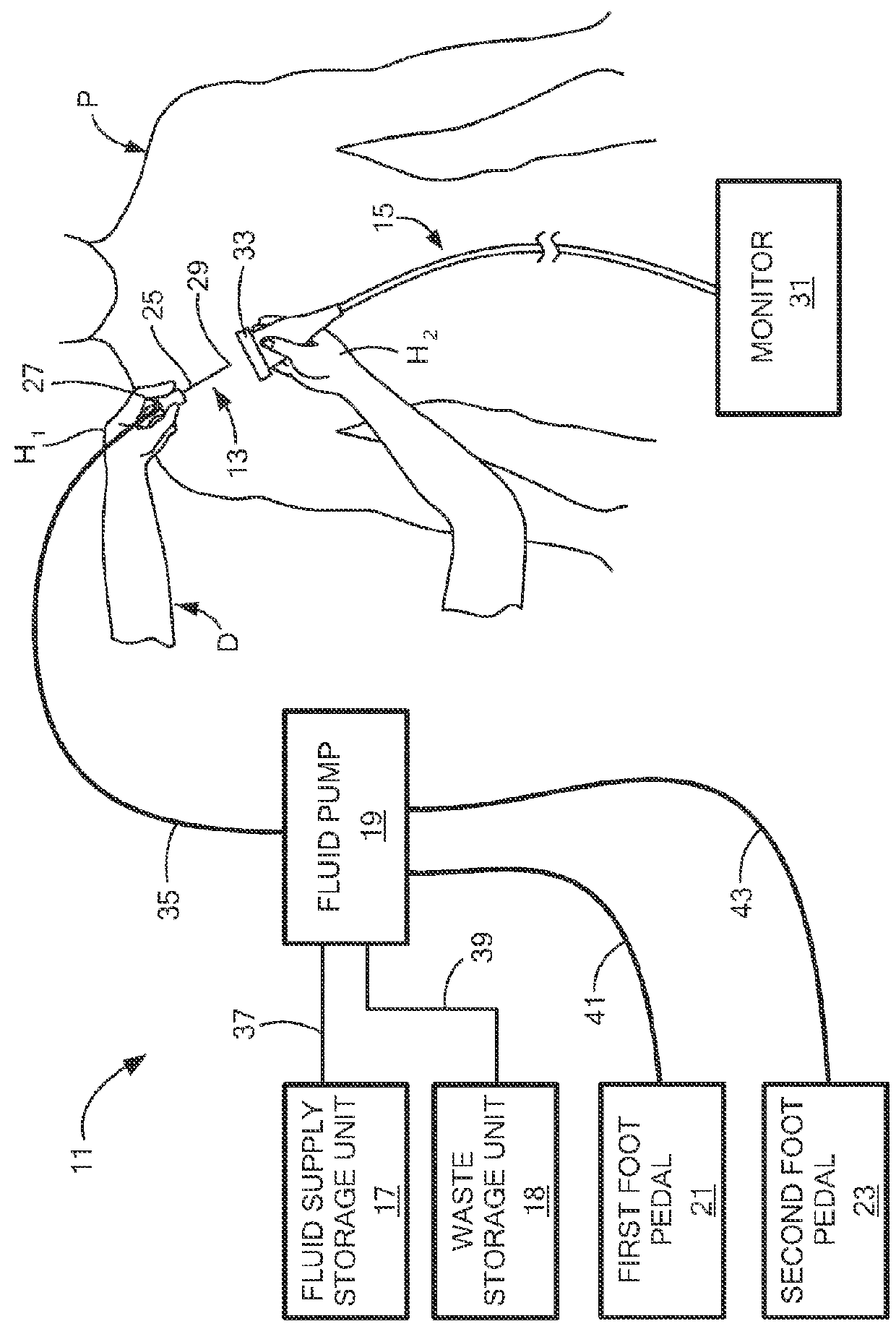
[0081]Referring now to FIG. 1, there is schematically shown a system according to the present invention for controllably administering fluid to a patient and / or for controllably withdrawing fluid from the patient, the system being represented generally by reference numeral 11. System 11 is shown in FIG. 1 being used by a doctor D on a patient P.

[0082]System 11 may include one or more of an infusion needle assembly 13, a handheld ultrasound imager 15, a fluid supply storage unit 17, a waste storage unit 18, a fluid pump 19, a first foot pedal 21, and a second foot pedal 23. Each of the foregoing components will now be discussed further below.

[0083]Infusion needle assembly 13 may be conventional and may include an infusion needle 25 and a needle hub 27. Infusion needle 25, which may be a generally tubular member having a sharpened distal end 29, may have a length of, for example, approximately 25 mm to approximately 150 mm and may have an outer diameter of, for example, approximately ...

second embodiment

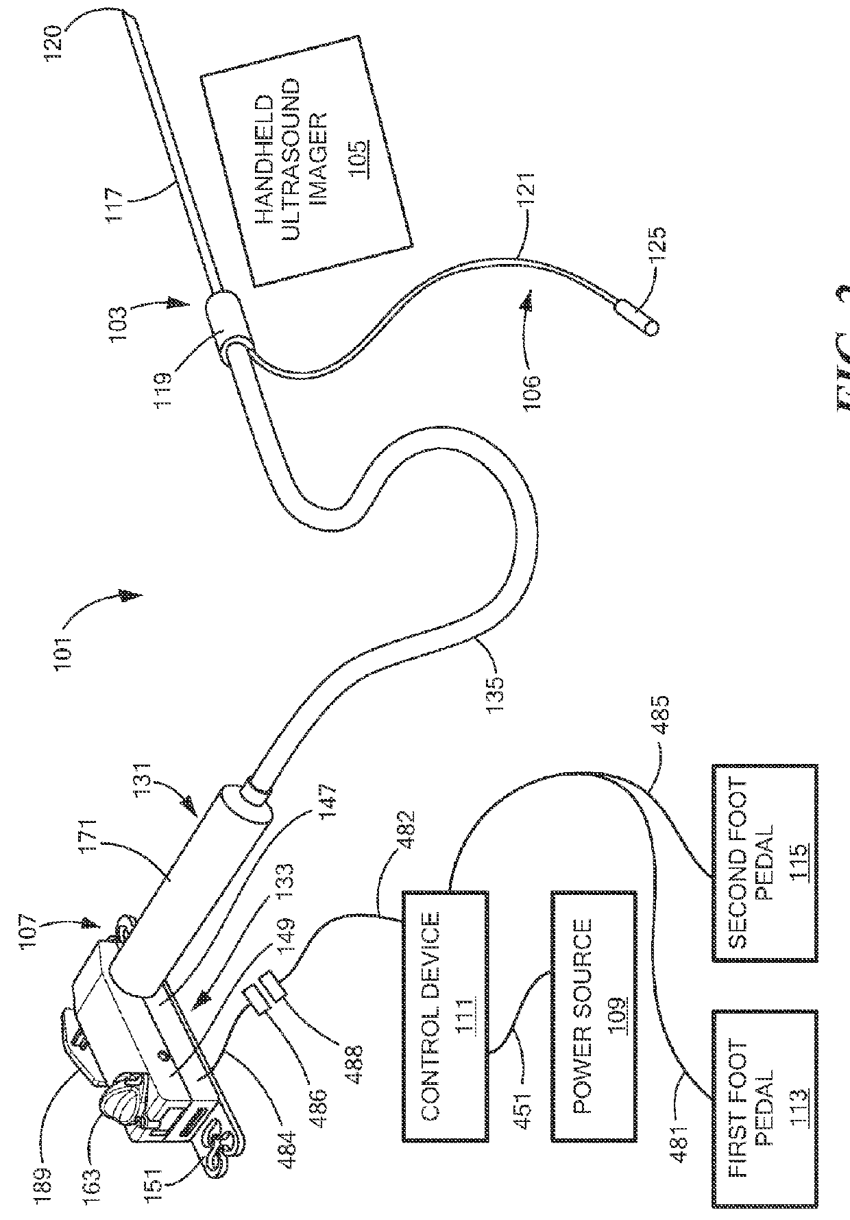
[0099]Referring now to FIG. 2, there is shown a perspective view, partly schematic, of a system according to the present invention for controllably administering fluid to a patient and / or for controllably withdrawing fluid from the patient, the system being represented generally by reference numeral 101.

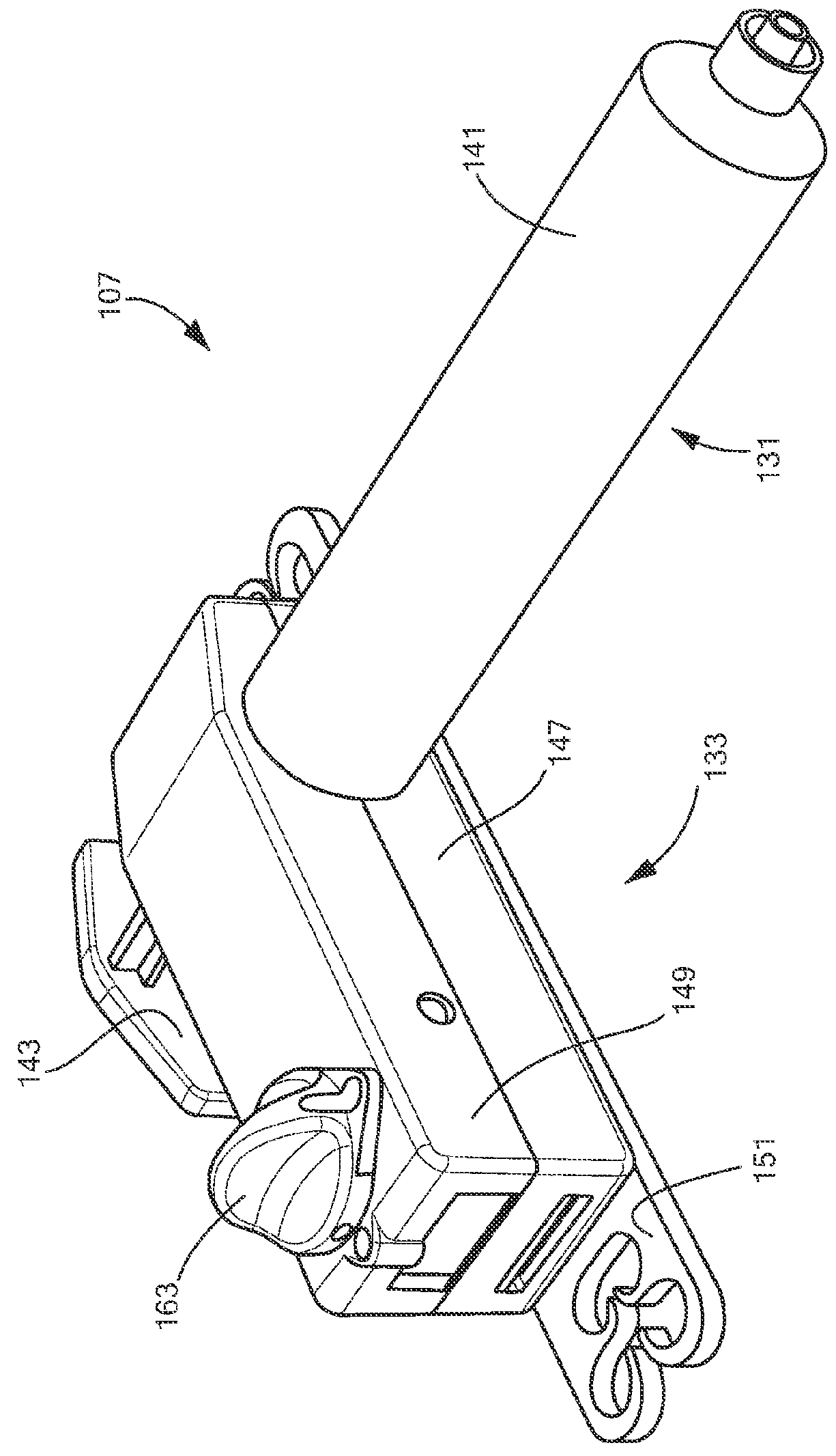
[0100]System 101 may include one or more of an infusion needle assembly 103, a handheld ultrasound imager 105, a nerve stimulator lead 106, a syringe / pump assembly 107, a power source 109, a control device 111, a first foot pedal 113, and a second foot pedal 115. Each of the foregoing components will now be discussed further below.

[0101]Infusion needle assembly 103, which may be similar to infusion needle assembly 13, may be conventional and may include an infusion needle 117 and a needle hub 119. Infusion needle 117 may be a generally tubular member having a sharpened distal end 120 and may have a length of, for example, approximately 25 mm to approximately 150 mm and an outer diame...

third embodiment

[0156]Referring now to FIG. 27, there is shown a perspective view, partly schematic, of a system according to the present invention for controllably administering fluid so a patient and / or for controllably withdrawing fluid from the patient, the system being represented generally by reference numeral 701.

[0157]System 701 may include one or more of an infusion needle assembly 703, a handheld ultrasound imager 705, a nerve stimulator lead 706, a fluid receptacle 707, a peristaltic pump 709, and a foot pedal assembly 713. Each of the foregoing components will now be discussed further below.

[0158]Infusion needle assembly 703, which may be similar to infusion needle assembly 13, may be conventional and may include an infusion needle 717 and a needle hub 719. Infusion needle 717 may be a generally tubular or otherwise finger graspable member having a sharpened distal end 720 and may have a length of, for example, approximately 25 mm to approximately 150 mm and an outer diameter of, for ex...


PUM


Abstract

Method and system for controllably administering and/or withdrawing fluid from a patient. In one embodiment, the system may include a needle assembly, an ultrasound imager, a fluid supply storage unit, a waste storage unit, a fluid pump, and a foot pedal assembly. A syringe may serve as the fluid supply storage unit and the waste storage unit. The pump may include a bi-directional motor and a gear coupled to the motor. The gear may be engageable with a rack on the syringe plunger to drive the plunger either for fluid aspiration or infusion. Depression of one portion of the foot pedal assembly causes the motor to drive the gear in one direction, and depression of another portion of the foot pedal assembly causes the motor to drive the gear the other direction. The system may include a control device to keep pressure in the fluid path from exceeding a limit.

Description

BACKGROUND OF THE INVENTION[0001]The present invention relates generally to the administration of fluid to a patient or to the withdrawal of fluid from a patient and relates more specifically to a method and system for controllably administering fluid to a patient and / or for controllably withdrawing fluid from the patient.[0002]There are many situations in which it may be desirable to administer one or more fluids to a patient or to withdraw one or more fluids from a patient. An example of one such situation involves the administration of regional anesthesia to a patient. In contrast to general anesthesia, which is a systemic sedation of a patient, regional anesthesia is the administration of medication to specific body regions by anesthetizing specific nerves, thereby permitting the patient to block pain and to be cognitively alert or conscious. Regional anesthesia may be used to treat pain during surgery and during post-surgery recovery and may also be used to provide patients wit...

Claims


Application Information

Patent Timeline
IPC IPC(8): A61M5/145A61M5/00A61M5/20
CPCA61M5/145A61M2205/12A61M5/002A61M5/20A61M5/14216A61M5/1452A61M5/14526A61M5/14546A61M5/16877A61M2205/502A61M2205/505A61M5/14232A61M19/00
Inventor ADANIYA, GEORGEDONNELLY, HOWARDMATHEWS, ERICTAYLOR, HAYDENWHITEHEAD, ANDREW
Owner MEDOVATE LTD
Why Eureka
Try Eureka