Mobile collaborative robot

a robot and robot technology, applied in the field of mobile collaborative robots, can solve the problems of increasing the manufacturing cost but also the troublesome determination operation, not taking into account the contact between a human and a carriage, and it is difficult to precisely detect the contact of an obstacle by the shock sensor

Active Publication Date: 2016-02-04
FANUC LTD
View PDF21 Cites 24 Cited by
  • Summary
  • Abstract
  • Description
  • Claims
  • Application Information

AI Technical Summary

Problems solved by technology

However, the robot disclosed in Japanese Unexamined Patent Publication No. 2011-110630 is not a mobile robot, and accordingly, contact between a human and a carriage is not taken into consideration.
However, in order to precisely detect the contact of the self-travelling robot with an obstacle by the shock sensor, it is necessary to provide a large number of shock sensors, thus resulting in not only an increase of the manufacturing cost but also troublesome operations required to determine the optimal mounting positions and postures of the shock sensors.
In particular, in an industrial robot, such as a perpendicular articulated robot, when the robot operates, the posture of the robot changes in various ways, and accordingly, when the industrial robot is a self-travelling-type robot, it is difficult to precisely detect contact thereof with an obstacle by the shock sensors.

Method used


Image

  • Mobile collaborative robot
  • Mobile collaborative robot
  • Mobile collaborative robot

Examples


Embodiment Construction

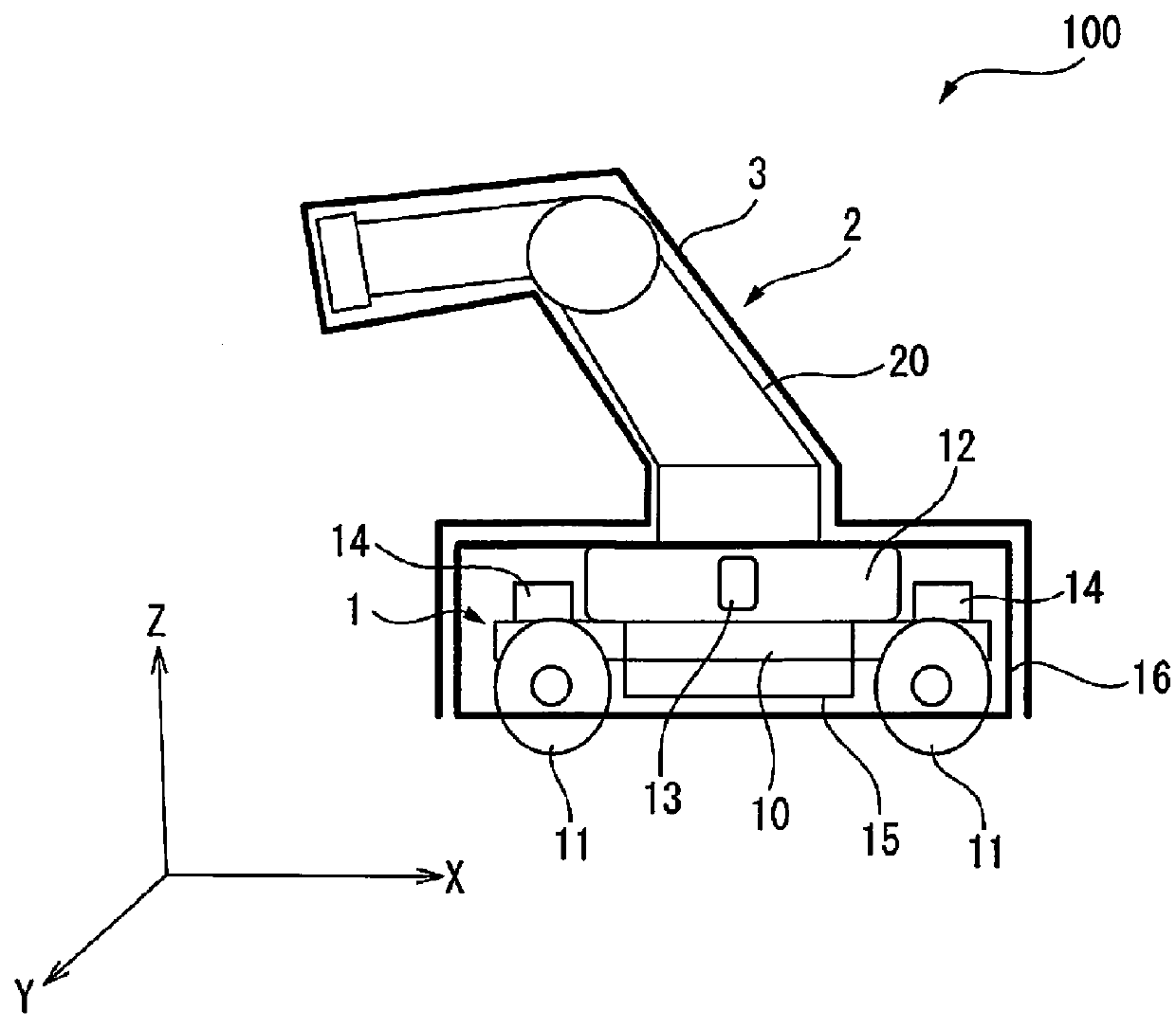
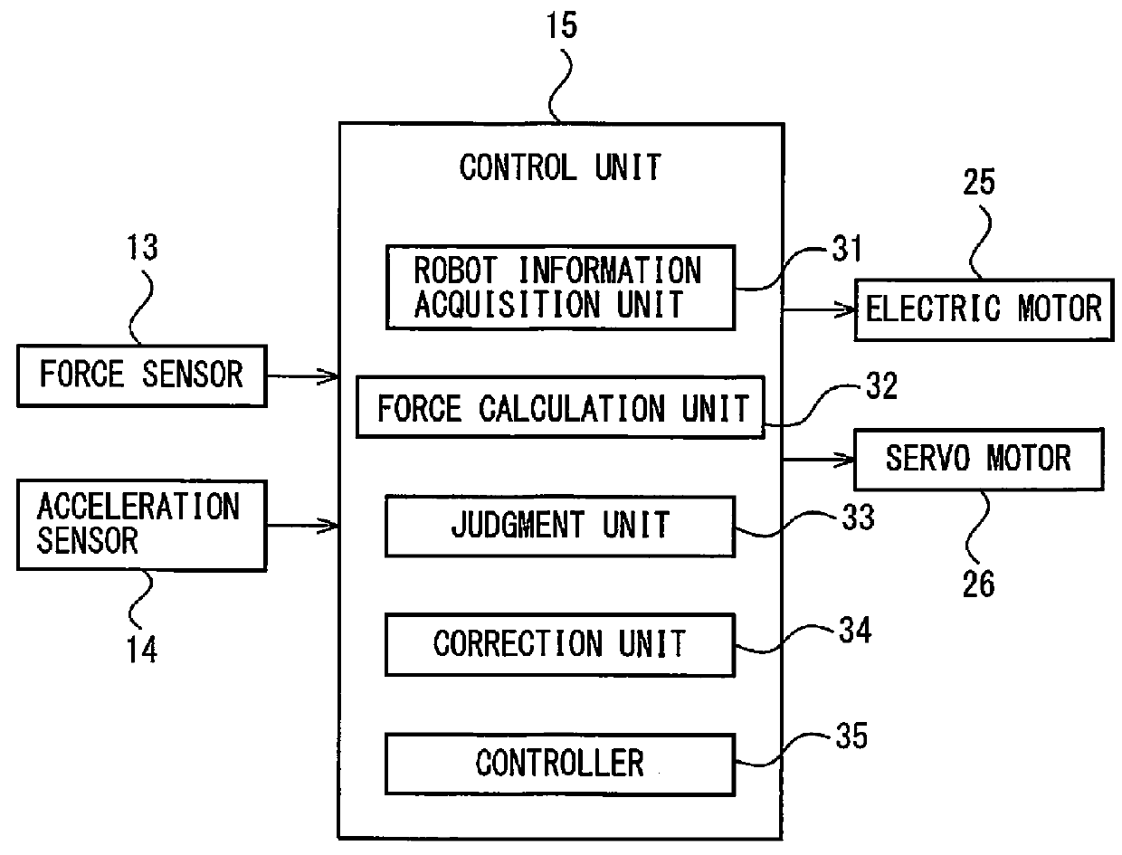
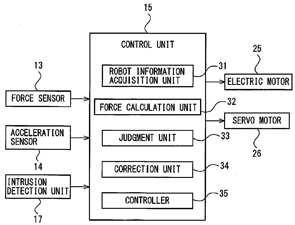
[0016]Embodiments of the present invention will be discussed below with reference to FIGS. 1 to 7. FIG. 1 is a side view which schematically shows a mobile collaborative robot 100 according to an embodiment of the present invention. The mobile collaborative robot 100 is composed of a movable carriage 1, and a robot 2 placed on the carriage 1, so that the robot 2 is movable in accordance with the movement of the carriage 1. Note that in the following the mobile collaborative robot 100 is referred to merely as a robot, and the robot 2 is referred to as a robot main body to distinguish the robot 2 from the robot 100. Moreover, in the following discussion, for convenience' sake, the length direction (X direction) of the carriage 1, the width direction (Y direction), and the height direction (Z direction) are defined to be the forward / backward direction, the right / left direction, and the upward / downward direction, respectively. The components of the robot will be explained in accordance ...


PUM


Abstract

A mobile collaborative robot includes a force sensor which is provided on a robot support on a carriage, a robot information acquisition unit which acquires robot information including posture information of the robot main body and load information of a load acting on the robot main body, a force calculation unit which calculates the external force acting on the robot support based on the robot information, and a judgment unit which judges that the mobile collaborative robot has come into contact with a human when a difference between the external force detected by the force sensor and the external force calculated by the force calculation unit is above a predetermined value α or when a difference between the amount of change in the detected external force and the amount of change in the calculated external force is above a predetermined value α1.

Description

BACKGROUND OF THE INVENTION[0001]1. Technical Field[0002]The present invention relates to a mobile collaborative robot which operates in cooperation with a human.[0003]2. Description of Related Art[0004]In a mobile collaborative robot in which the robot is mounted on a carriage so as to be movable, there is a possibility that a human makes contact with the robot or the carriage, and accordingly, it is necessary to enhance the safety upon contact. Regarding contact with a robot, in conventional devices, a force sensor is provided on the base of the robot to detect the contact of the robot with the external environment (e.g., Japanese Unexamined Patent Publication No. 2011-110630). However, the robot disclosed in Japanese Unexamined Patent Publication No. 2011-110630 is not a mobile robot, and accordingly, contact between a human and a carriage is not taken into consideration.[0005]A self-travelling robot is known wherein a shock sensor is provided on a peripheral surface of a main bo...

Claims


Application Information

Patent Timeline
Patent Type & Authority Applications(United States)
IPC IPC(8): B25J9/16
CPCB25J9/1694Y10S901/01Y10S901/50Y10S901/46Y10S901/02B25J5/007B25J13/085B25J13/088B25J19/0075B25J19/06
Inventor TANABE, YOSHIKIYOHASHIMOTO, YOSHIKI
Owner FANUC LTD
Why Eureka
Try Eureka