Apparatus and Method for Storing Energy

a technology of energy storage and apparatus, applied in the direction of steam accumulators, steam engine plants, hot gas positive displacement engine plants, etc., can solve the problems of inflexibility in power generation provided, cost of energy storage, flexibility and energy densities achievable, etc., to eliminate any marching, and reduce the marching rate

Inactive Publication Date: 2016-02-04
ENERGY TECH INST
View PDF5 Cites 48 Cited by
  • Summary
  • Abstract
  • Description
  • Claims
  • Application Information

AI Technical Summary

Benefits of technology

[0034]TL1 will naturally decrease progressively with charging over time and increase progressively with discharging over time, unless steps are taken e.g. to add external heat or thermal ballast. A marching temperature is desirable on the LP side and HP side during condensation and vaporisation for a more reversible and hence efficient system. As mentioned earlier, thermal ballast will reduce the rate of marching on either side, if required. External heat from an auxiliary system added during charging may also reduce the rate of marching, or, on the LP side, totally eliminate any marching. The system may therefore be configured such that TL1 of L1 is maintained substantially constant for some or all of the storage mode, and / or for some or all of the recovery mode. In that case, there is little advantage to providing a regenerator disposed between the power machinery and the liquid stored in the first vessel.
[0035]The LP side vessel may be connected to a supply tank (e.g. infinite supply) that feeds in and out working fluid (e.g. continuously) such that some can be replaced with working fluid at a different temperature; this involves mass exchange and temperature exchange with the surroundings and may be used to reduce or eliminate marching of the L1 temperature and pressure.

Problems solved by technology

The inflexibility in power generation provided by nuclear, solar and wind based renewable energy sources has posed a number of problems in using these technologies to provide a major part of a national or regional power grid.
One such problem is the need to store and recover electrical energy to prevent disruptions to the electricity supply in the light of the variable energy supply, with particular issues being the cost of energy storage, the flexibility and the energy densities achievable.

Method used


Image

  • Apparatus and Method for Storing Energy
  • Apparatus and Method for Storing Energy
  • Apparatus and Method for Storing Energy

Examples


first embodiment

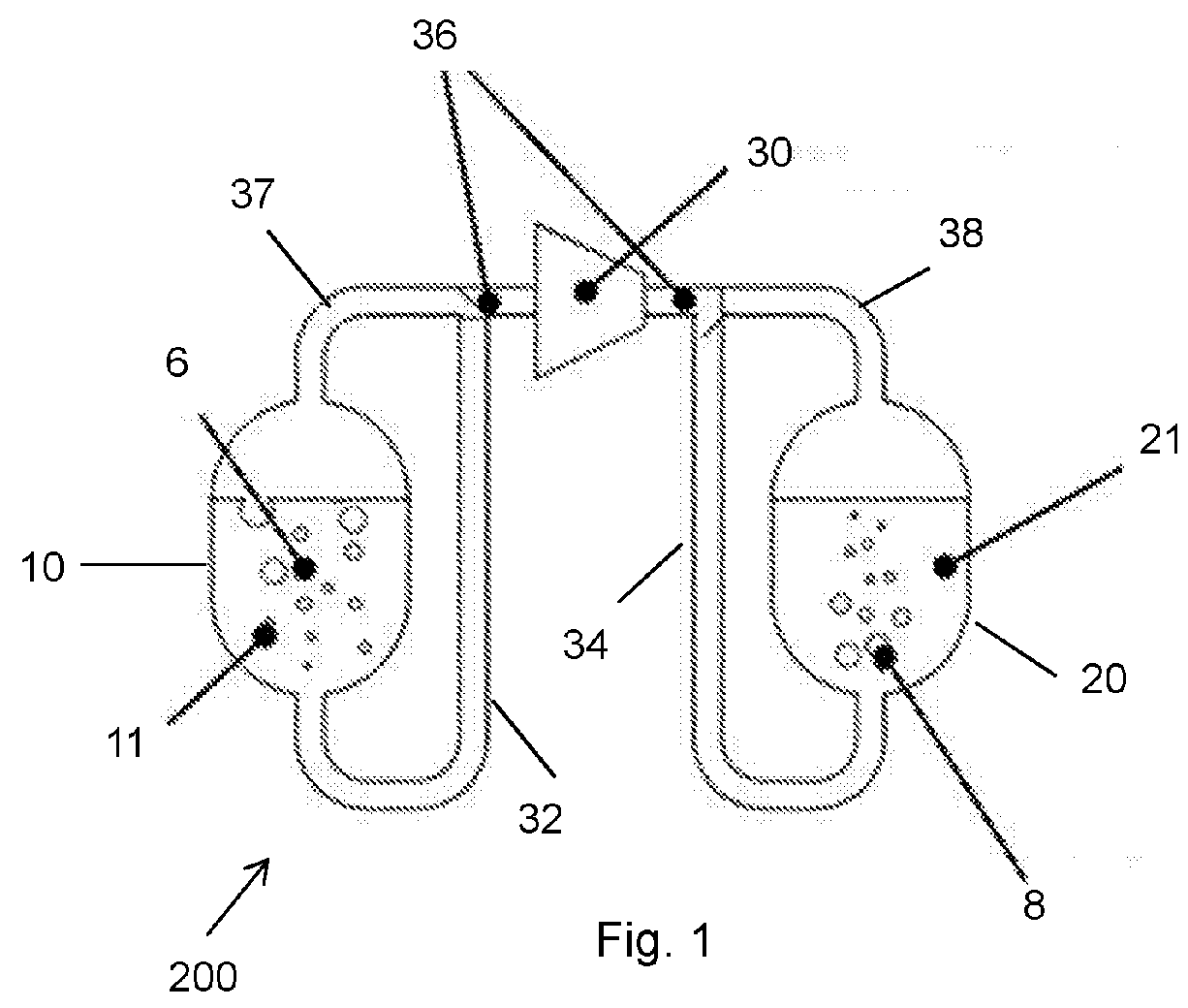
[0091]FIG. 4 illustrates an energy storage system in accordance with the present invention.

[0092]This system 202 may comprise all the components of the basic system as described in relation to FIGS. 1 to 3, but further comprises a regenerator 50 on the HP side of the system comprising a solid gas permeable thermal storage medium through which the gas passes for direct transfer of thermal energy to and from the solid medium. The function of this regenerator is to capture superheat on charging and return it on discharging and this is done in accordance with the present invention in a manner that reduces irreversibilities in the respective heat transfer processes.

[0093]The regenerator 50 is inserted between the compressor / expander 30 and the hot tank 20 so that it is located in the path of both the condensing vapour on charging and the returning, evaporating vapour on discharging, with the arrangement configured to allow any condensing vapour to reach the hot tank 50. In the FIG. 4 sys...

second embodiment

[0146]FIG. 5 illustrates an energy storage system 204 in accordance with the present invention, comprising a further regenerator 40 on the lower pressure LP side of the system to further improve round trip efficiency. The addition of this LP side regenerator ensures that all vapour compressed or expanded is dry, i.e., contains no liquid droplets.

[0147]Storing some superheat from the vapour on the LP (cold) side is very desirable. This is achieved by the addition of a sensible heat store (regenerator) between the cold liquid vessel and the compressor / expander. Consider the effect of reducing cold side pressure by drawing some vapour from the cold side with the compressor. The liquid in the cold vessel starts in equilibrium with the vapour that is also present within the vessel. As vapour is drawn off by the compressor, the liquid in the vessel boils and the latent heat required for this process, coming from the body of the liquid, results in a fall in the liquid temperature. The sens...

sixth embodiment

[0176]FIG. 15 shows an energy storage system in accordance with the present invention, which illustrates integration of a waste heat recapture sub-system.

[0177]Irreversibilities in an energy storage and recovery system will result in the generation of entropy and hence an overall increase in the mean temperature of such a system. In the illustrated system, water / steam is used as the working fluid and the storage system is integrated with a domestic hot water system. This takes advantage of the ambient pressure boiling characteristics of water to dispose of any waste heat build-up that arises due to such irreversibilities within the system.

[0178]The cold liquid store 10 is connected to the domestic hot water tank 321 via a non-return valve 323 that only allows flow to run towards the hot water tank. The domestic tank 321 is at close to atmospheric pressure and so, as the pressure of the cold liquid tank 10 approaches the pressure within the domestic water tank, if the liquid tank abs...


PUM


Abstract

In an energy storage and recovery system, working fluid from a first vessel is compressed by power machinery and passes, via a regenerator, into a second vessel, where it is forced to condense, the temperature and pressure of the saturated working liquid/vapour mixture continuously rising during storage. The stored energy is recovered by the vapour returning through the regenerator and power machinery where it expands to produce work before condensing back into the first vessel. The regenerator comprises a gas permeable, solid thermal storage medium which, during storage, stores superheat and some latent heat from the vapour passing through it in respective downstream regions that exhibit continuously increasing temperature profiles during storage and a small temperature difference with the surrounding vapour, thereby minimising irreversible losses during the thermal energy transfers.

Description

FIELD OF THE INVENTION[0001]This invention relates to a system and method for storing and recovering energy, especially for storing and recovering energy using thermal storage.BACKGROUND TO THE INVENTION[0002]The inflexibility in power generation provided by nuclear, solar and wind based renewable energy sources has posed a number of problems in using these technologies to provide a major part of a national or regional power grid. One such problem is the need to store and recover electrical energy to prevent disruptions to the electricity supply in the light of the variable energy supply, with particular issues being the cost of energy storage, the flexibility and the energy densities achievable. A number of energy storage technologies are now being developed to address such issues including pumped hydro storage, flywheel storage, compressed air energy storage CAES (including isothermal and adiabatic CAES) and pumped heat energy storage, as in accordance with Applicant's earlier app...

Claims


Application Information

Patent Timeline
Patent Type & Authority Applications(United States)
IPC IPC(8): F01K3/12
CPCF01K3/12F01K3/006F01K3/06
Inventor HOWES, JONATHAN SEBASTIANMACNAGHTEN, JAMES
Owner ENERGY TECH INST
Why Eureka
Try Eureka