

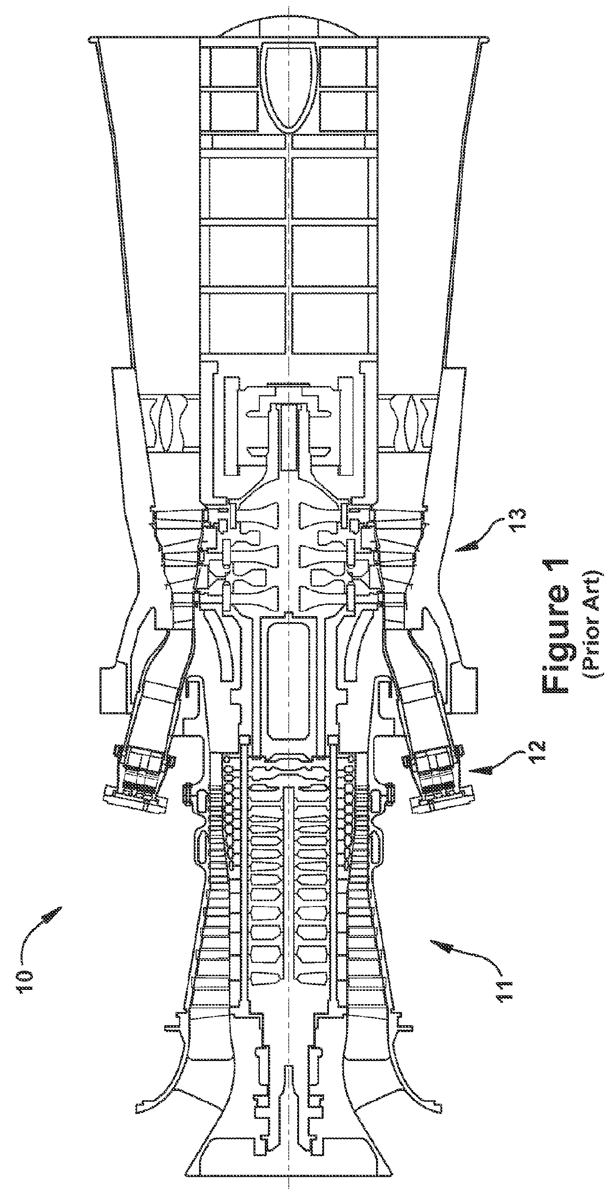
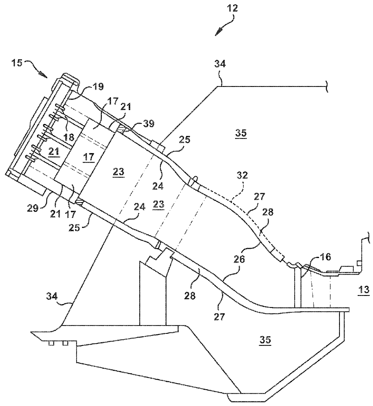
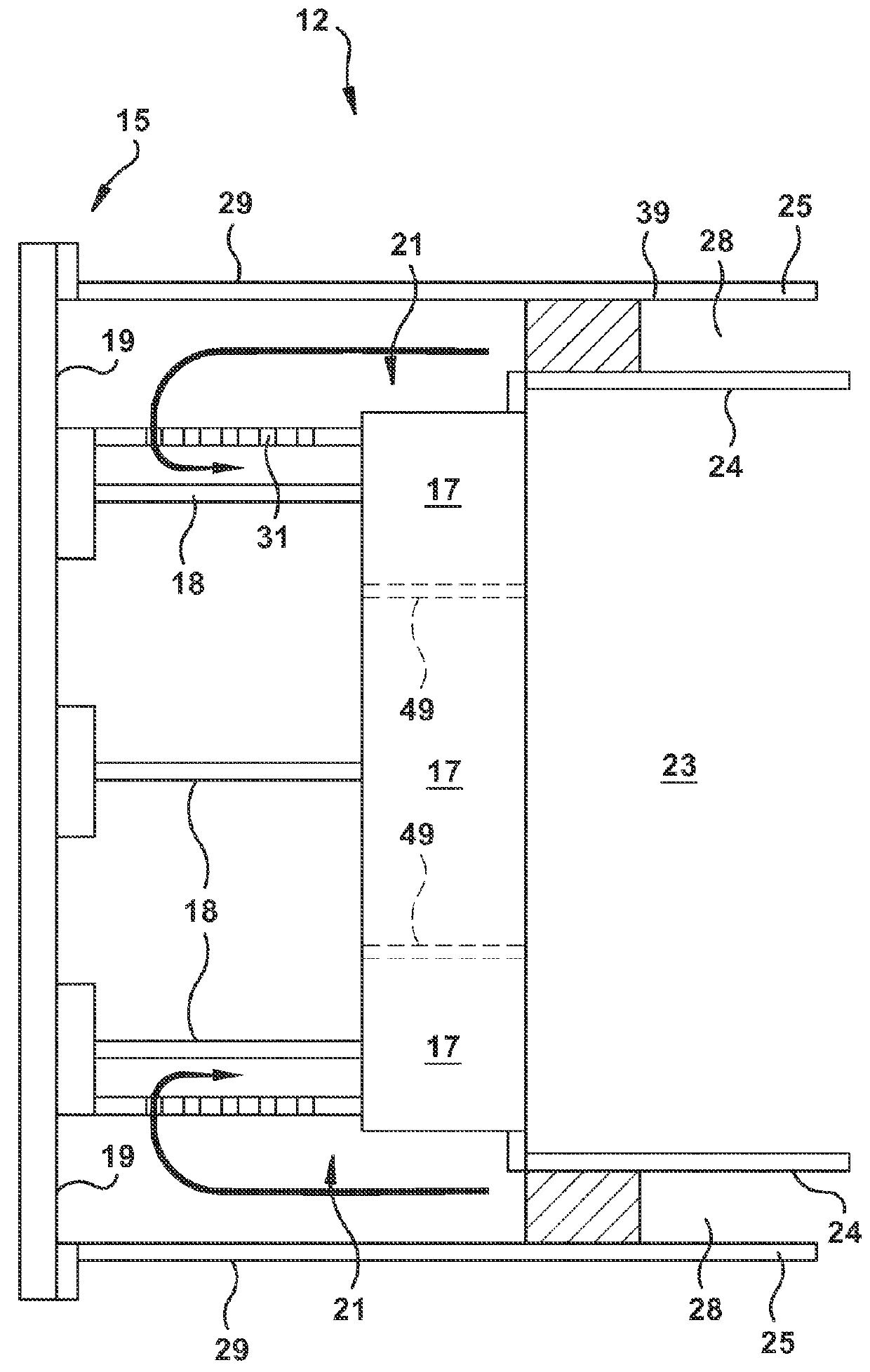
Combustor nozzles in gas turbine engines
a gas turbine engine and combustion system technology, applied in the combustion process, hot gas positive displacement engine plant, lighting and heating apparatus, etc., can solve the problems of cracking and deformation, expansion of the outer wall more than the mixing tube, and high strain level developmen
- Summary
- Abstract
- Description
- Claims
- Application Information
AI Technical Summary
Benefits of technology
Problems solved by technology
Method used
Image

Examples
Embodiment Construction
[0019]In the following text, certain terms have been selected to describe the present invention. To the extent possible, these terms have been chosen based on the terminology common to the field. Still, it will be appreciate that such terms often are subject to differing interpretations. For example, what may be referred to herein as a single component, may be referenced elsewhere as consisting of multiple components, or, what may be referenced herein as including multiple components, may be referred to elsewhere as being a single component. In understanding the scope of the present invention, attention should not only be paid to the particular terminology used, but also to the accompanying description and context, as well as the structure, configuration, function, and / or usage of the component being referenced and described, including the manner in which the term relates to the several figures, as well as, of course, the precise usage of the terminology in the appended claims.
[0020...
PUM
 Abstract
Description
Claims
Application Information