Spool braking device and fishing reel
a braking device and spool technology, applied in fishing reels, applications, fishing, etc., can solve the problems of fishing line becoming tangled, space for this movement also needed, and certain weight is needed, so as to reduce the weight and the size of the spool braking device
- Summary
- Abstract
- Description
- Claims
- Application Information
AI Technical Summary
Benefits of technology
Problems solved by technology
Method used
Image
Examples
first embodiment
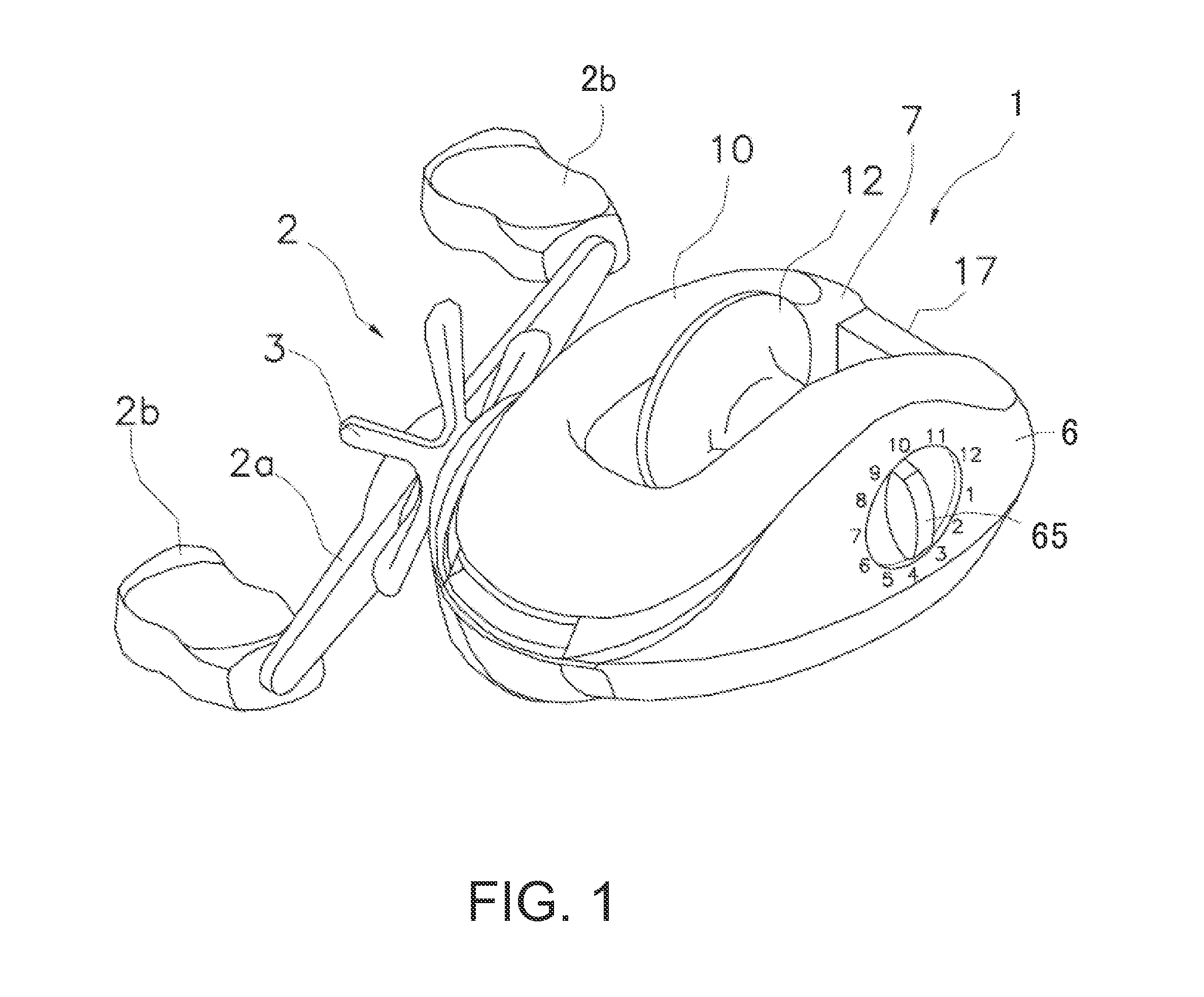
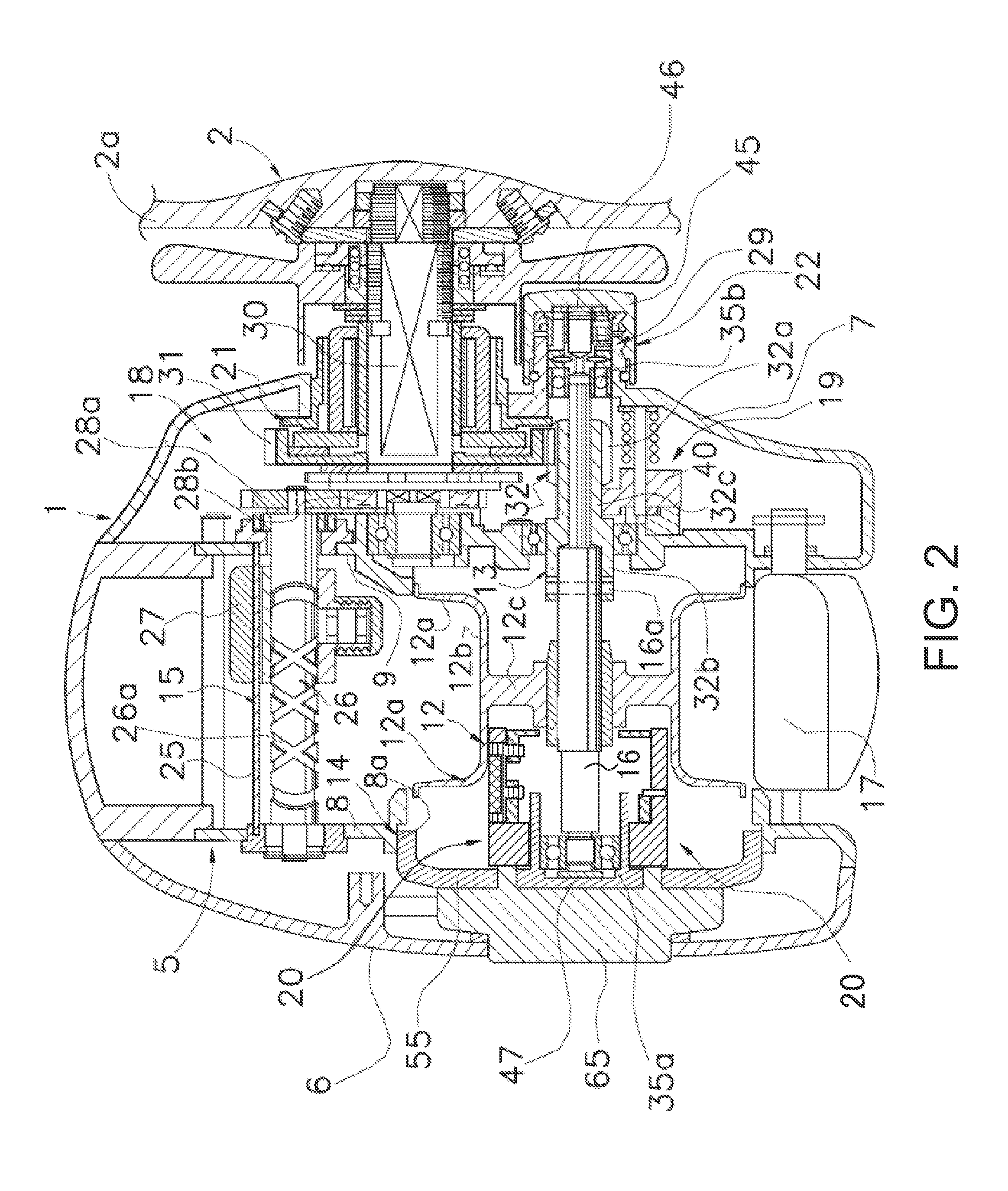
[0035]FIG. 1 is a perspective view of a fishing reel according to the first embodiment of the present invention. This fishing reel is a dual-bearing reel that is used mainly for lure fishing. This dual-bearing reel comprises a reel body 1, a handle 2 disposed on the side of the reel body 1, and a star drag 3 for drag adjustment disposed on the reel body 1 side of the handle 2. A spool 12 onto which fishing line is wound is rotatably supported by the reel body 1. It is possible to wind the fishing line by turning the handle 2 to rotate the spool 12. The handle 2 comprises a plate-like arm portion 2a and a pair of grips 2b rotatably mounted to the ends of the arm portion 2a.
[0036]The fishing line is usually stretched from the spool 12 towards the left front side in FIG. 1. As shown in FIG. 1, the left front side is referred to as the front of the reel body 1, and the right rear side is referred to as the rear. A clutch operation lever 17 is disposed on the rear of the reel body 1. By...
modified example
[0074]FIG. 7 is a conceptual diagram showing the operation of the spool braking device according to a modified example of the first embodiment. In this modified example, a rack and pinion is used, instead of the retaining member 61, as a cam and the engagement member 63 to rotate the magnet 51. In FIG. 7, a tooth profile is represented as a rough sketch. The tooth edge is represented by the thick solid lines, the pitch is represented by the dashed lines, and the tooth bottom is represented by the thin solid lines.
[0075]The retaining member 71 that holds the magnet 51 is a pinion on the periphery of which are formed outer teeth 71a toward the rotating surface of the spool 12. The magnet 51 can be sufficiently rotated a maximum of 90, so that the outer teeth 71a do not need to be formed around the entire circumference. The retaining member 71 is rotatably supported by a support ring 62 via a shaft (support portion) that passes through the center of the magnet 51, in the same way as in...
second embodiment
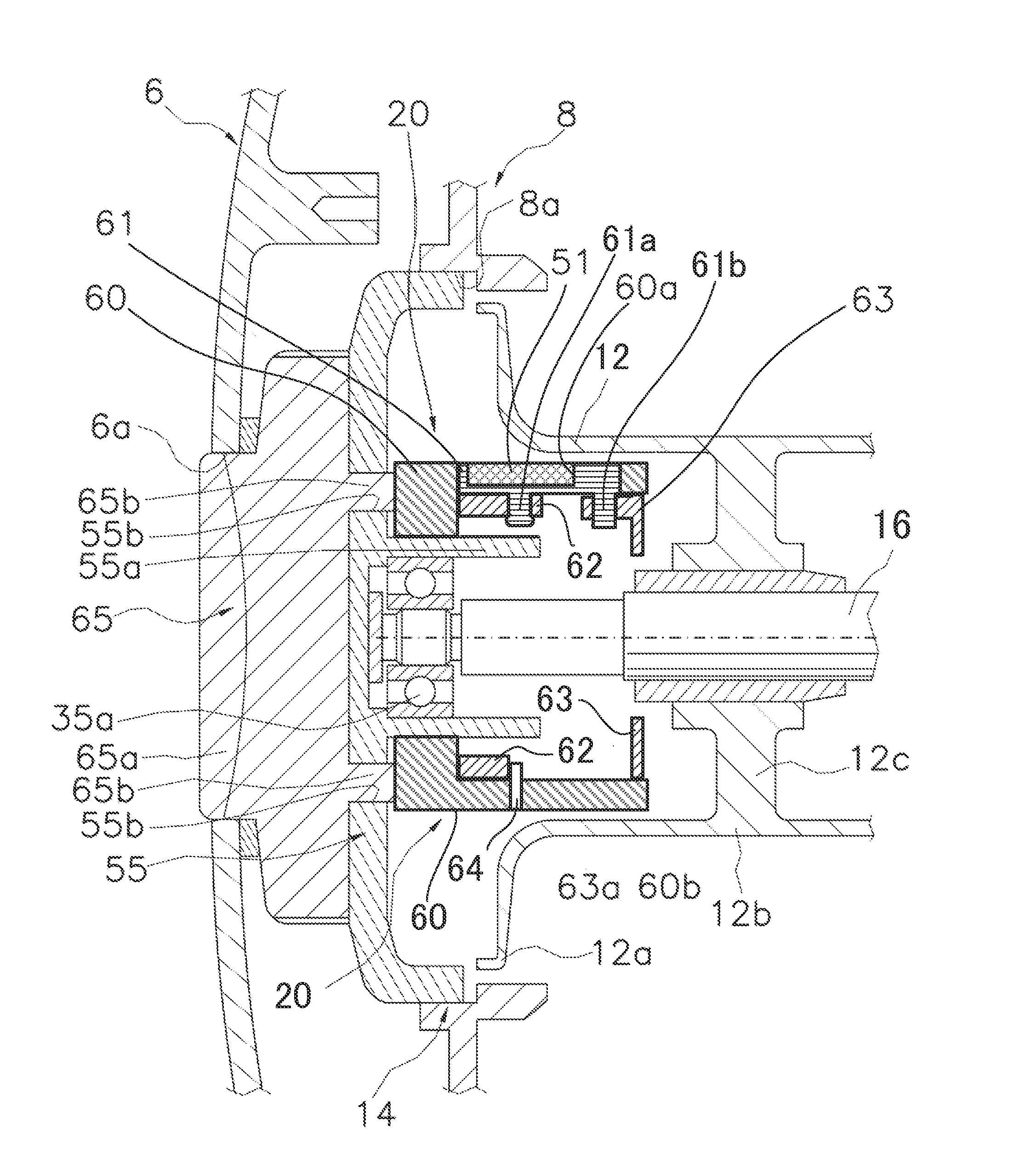
[0081]FIG. 8 is a cross-sectional view of the spool braking device according to the second embodiment of the present invention. In the second embodiment, the magnet 51 is pivotably supported around an axis that is parallel to the surface of the conductor that faces the magnet 51. Then, the magnet 51 is pivoted in a direction in which both the N-pole and the S-pole come close in the rotational circumferential direction of the conductor via the rotation of the conductor. The magnet 51 comprises an N-pole and an S-pole on the surface of the conductor that faces the magnet 51, as in the first embodiment. The spool 12 is also a conductor in the second embodiment.
[0082]In FIG. 8, the portions of the magnet 51, the retaining member 81, etc. are not in the cross section. The magnet 51 comprises an N-pole and an S-pole on a surface that faces the rotating surface of the spool 12. The rotating surface is the inner peripheral surface of the line winding cylinder part 12b of the spool 12. A sup...
PUM
 Abstract
Description
Claims
Application Information
 - R&D
- Intellectual Property
- Life Sciences
- Materials
- Tech Scout
- Unparalleled Data Quality
- Higher Quality Content
- 60% Fewer Hallucinations
Browse by: Latest US Patents, China's latest patents, Technical Efficacy Thesaurus, Application Domain, Technology Topic, Popular Technical Reports.
© 2025 PatSnap. All rights reserved.Legal|Privacy policy|Modern Slavery Act Transparency Statement|Sitemap|About US| Contact US: help@patsnap.com


