Fuel supply device, fuel supply method and boat propulsion device

a fuel supply device and fuel supply technology, applied in the direction of valve details, fluid pressure control, special dispensing means, etc., can solve the problems of fuel pump idleness, insufficient negative pressure in the sub fuel tank, oil-film seal not provided inside the fuel pump, etc., and achieve the effect of efficient sucking

Active Publication Date: 2016-02-11
YAMAHA MOTOR CO LTD
View PDF0 Cites 6 Cited by
  • Summary
  • Abstract
  • Description
  • Claims
  • Application Information

AI Technical Summary

Benefits of technology

[0008]In the fuel supply device according to a preferred embodiment of the present invention, when the fuel pump is driven and the negative pressure is produced in the pump suction port, the vaporized-liquid fuel mixture produced in the vaporized-liquid fuel mixture suction portion is sucked into the fuel pump through the pump suction port because the fuel storage region is a sealed region. Thus, the vaporized fuel is efficiently sucked out of the fuel storage region. Accordingly, even when the engine is restarted after a dead soak, the negative pressure is promptly produced in the fuel storage region located upstream of the fuel pump. Further, an oil-film seal is maintained inside the fuel pump by sucking the liquid fuel into the fuel pump from the fuel storage region. As a result, the fuel pump continuously exerts its pump action. Thus, the liquid fuel is quickly drawn into the fuel tank, and the fuel is continuously supplied downstream of the fuel pump.

Problems solved by technology

However, while sucking only the gas, the fuel pump idles.
Thus, sufficient negative pressure cannot be produced in the sub fuel tank.
Further, an oil-film seal is not provided inside the fuel pump.
Thus, the fuel pump cannot sufficiently exert its pump action.
As a result, the liquid fuel cannot be quickly drawn into the sub fuel tank.

Method used


Image

  • Fuel supply device, fuel supply method and boat propulsion device
  • Fuel supply device, fuel supply method and boat propulsion device
  • Fuel supply device, fuel supply method and boat propulsion device

Examples


first preferred embodiment

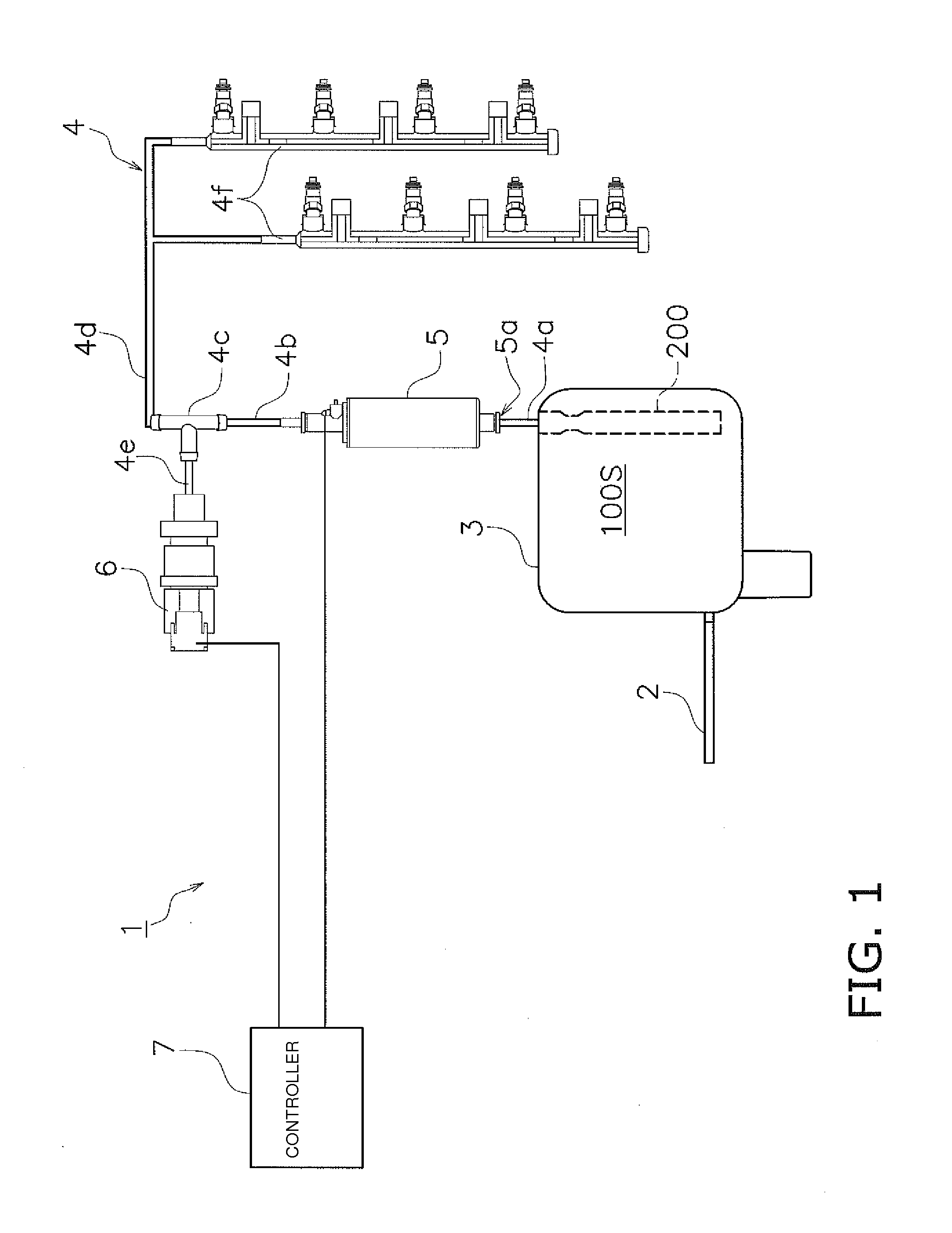
[0023]A structure of a fuel supply device 1 for supplying fuel to an engine will be hereinafter explained. FIG. 1 is a schematic diagram of a structure of the fuel supply device 1 according to a first preferred embodiment of the present invention.

[0024]The fuel supply device 1 includes a fuel supply pipe 2, a fuel tank 3, a fuel path 4, a fuel pump 5, a fuel pressure sensor 6, and a controller 7.

[0025]The fuel supply pipe 2 is connected to the fuel tank 3. The fuel supply pipe 2 directs the fuel to the fuel tank 3.

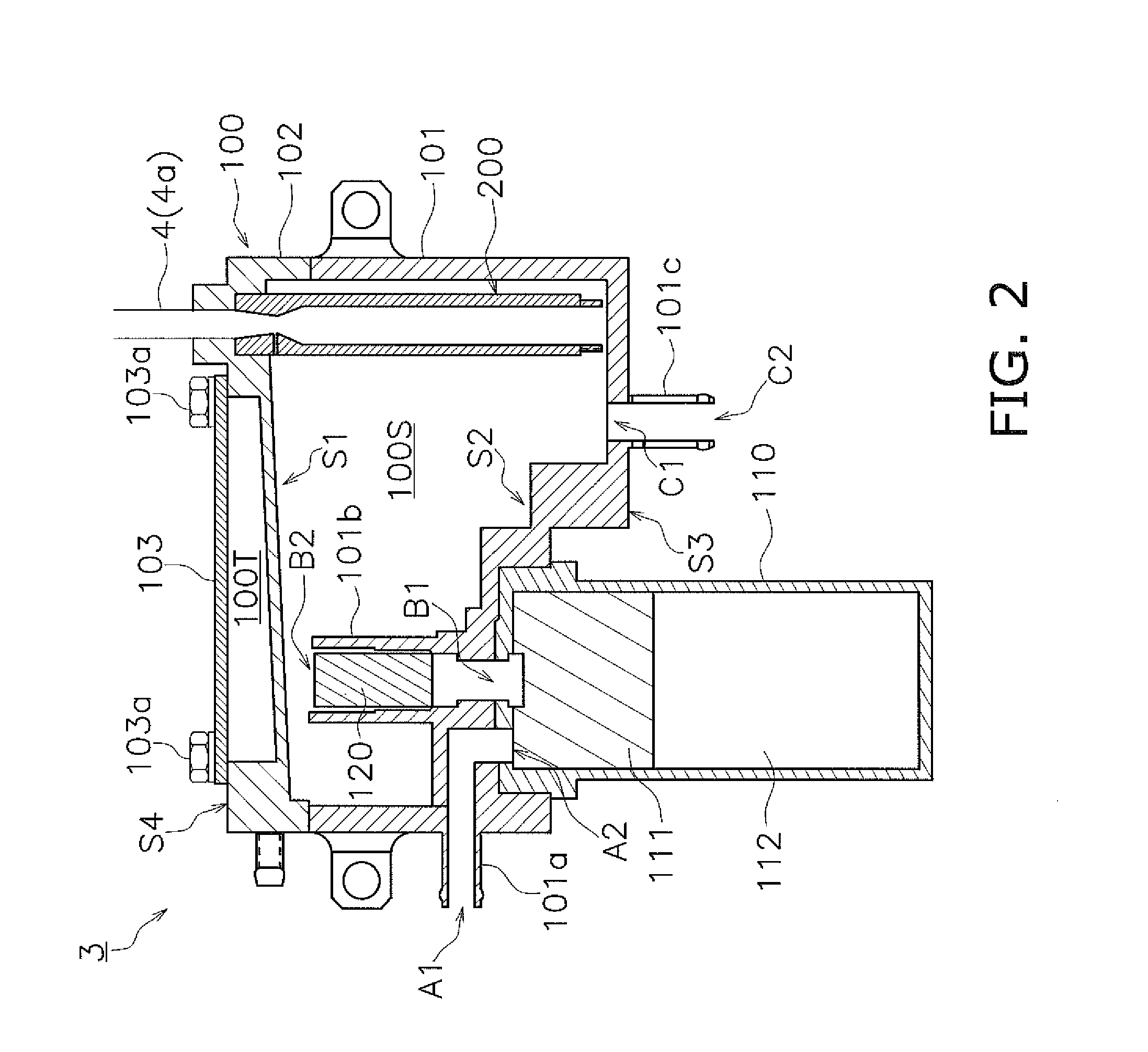
[0026]The fuel tank 3 includes a fuel storage region 100S configured to store the fuel fed thereto through the fuel supply pipe 2. The fuel storage region 100S is a sealed region with liquid tight properties and gas tight properties. The fuel storage region 100S does not include a port opened to the atmosphere. In the fuel storage region 100S, the vaporized fuel is produced as a result of vaporization of the liquid fuel. Thus, the fuel storage region 100S stores both the l...

second preferred embodiment

[0079]A structure of a fuel supply device 1A according to a second preferred embodiment of the present invention will be explained. FIG. 10 is a schematic diagram of the structure of the fuel supply device 1A according to the second preferred embodiment. The fuel supply device 1A is different from the fuel supply device 1 according to the first preferred embodiment in that the fuel supply device 1A is equipped with a regulator 8 and a return path 9 instead of the fuel pressure sensor 6 and the controller 7.

[0080]The regulator 8 is connected to the fuel path 4 (the fourth fuel hose 4e). The regulator 8 is configured to regulate the pressure of the fuel discharged from the fuel pump 5 to be a target value by releasing or diverting a surplus fuel existing in the fuel path 4 to the return path 9. The return path 9 is connected to the fuel tank 3 and the regulator 8. The fuel released from the regulator 8 returns to the fuel tank 3 through the return path 9. A self-priming pump is prefer...

third preferred embodiment

[0082]A structure of a fuel supply device 1B according to a third preferred embodiment of the present invention will be explained. FIG. 11 is a schematic diagram of the structure of the fuel supply device 1B according to the third preferred embodiment. The fuel supply device 1B is different from the fuel supply device 1 according to the first preferred embodiment in that the fuel supply device 1B utilizes a fuel tank 3B as a sub tank to store a fuel to be supplied to a vapor separator tank (hereinafter referred to as “VST”) 10.

[0083]The fuel supply device 1B includes the fuel tank 3B, a fuel pump 5B, and the VST 10.

[0084]The fuel tank 3B has a simple structure that is not provided with a filtration filter and so forth. The fuel tank 3B includes the fuel storage region 100S that is configured to store a fuel to be fed thereto through the fuel supply pipe 2. The fuel storage region 100S is a sealed region with liquid tight properties and gas tight properties. The fuel storage region 1...


PUM


Abstract

A fuel supply device includes a fuel tank, a fuel path, and a fuel pump. The fuel tank includes a fuel storage region including a sealed region configured to store a fuel. The fuel path is connected to an engine and the fuel tank. The fuel path includes a vaporized-liquid fuel mixture suction portion to suck a vaporized-liquid fuel mixture. The vaporized-liquid fuel mixture is produced by mixing the vaporized fuel into the liquid fuel. The vaporized fuel is produced from the liquid fuel stored in the fuel storage region. The fuel pump is disposed in the fuel path. The fuel pump is configured to produce a negative pressure in a pump suction port connected to the vaporized-liquid fuel mixture suction portion.

Description

BACKGROUND OF THE INVENTION[0001]1. Field of the Invention[0002]The present invention relates to a fuel supply device configured to supply fuel to an engine, a fuel supply method, and a boat propulsion device including the fuel supply device.[0003]2. Description of the Related Art[0004]Among fuel supply devices that supply fuel to an engine, one type of fuel supply device is equipped with a supply pump, a fuel tank, and a fuel pump, and is well known (see Japan Laid-open Patent Application Publication Nos. JP-A-H10-122077 and JPA-2002-130068). The supply pump is configured to pressurize and feed a liquid fuel to the fuel tank. The fuel tank includes a float, a float valve, and a fuel inflow pipe. The float floats on the liquid surface of the liquid fuel stored in the fuel tank. The float valve is connected to the float and normally closes the opening of the fuel inflow pipe. The float valve is configured to open the fuel inflow pipe when the position of the float becomes lower than ...

Claims


Application Information

Patent Timeline
Patent Type & Authority Applications(United States)
IPC IPC(8): B63H21/38B63H21/14F02B61/04G05D16/20
CPCB63H21/38G05D16/2013B63H21/14F02B61/045F02M37/0082F02M37/20
Inventor KADOBAYASHI, YOSHIYUKI
Owner YAMAHA MOTOR CO LTD
Why Eureka
Try Eureka