Physical quantity sensor, electronic device, and moving object

a technology of physical quantity sensor and electronic device, which is applied in the direction of flexible microstructure devices, instruments, surveying and navigation, etc., can solve the problems of complicated wire layout and difficulty in realizing the miniaturization of physical quantity sensors

Inactive Publication Date: 2016-02-11
SEIKO EPSON CORP
View PDF6 Cites 6 Cited by
  • Summary
  • Abstract
  • Description
  • Claims
  • Application Information

AI Technical Summary

Benefits of technology

[0037]Since the moving object includes the physical quantity sensor according to the application example described above, it is possible to realize miniaturization.

Problems solved by technology

Accordingly, a layout of the wires becomes complicated, and it is difficult to realize miniaturization of the physical quantity sensor, in some cases.

Method used


Image

  • Physical quantity sensor, electronic device, and moving object
  • Physical quantity sensor, electronic device, and moving object
  • Physical quantity sensor, electronic device, and moving object

Examples


modification examples

1.3. Modification Examples

[0135]Next, physical quantity sensors according to Modification Examples of the embodiment will be described with reference to the drawings. Regarding physical quantity sensors 200, 300, and 400 according to Modification Examples described below, the same reference numerals are used for the members having the same functions as the constituent elements of the physical quantity sensor 100 described above, and the description thereof will be omitted.

first modification example

1. First Modification Example

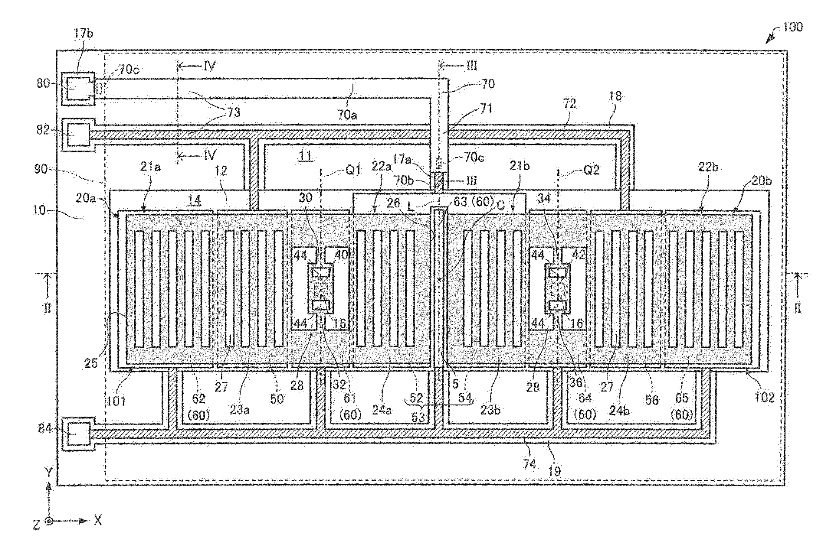
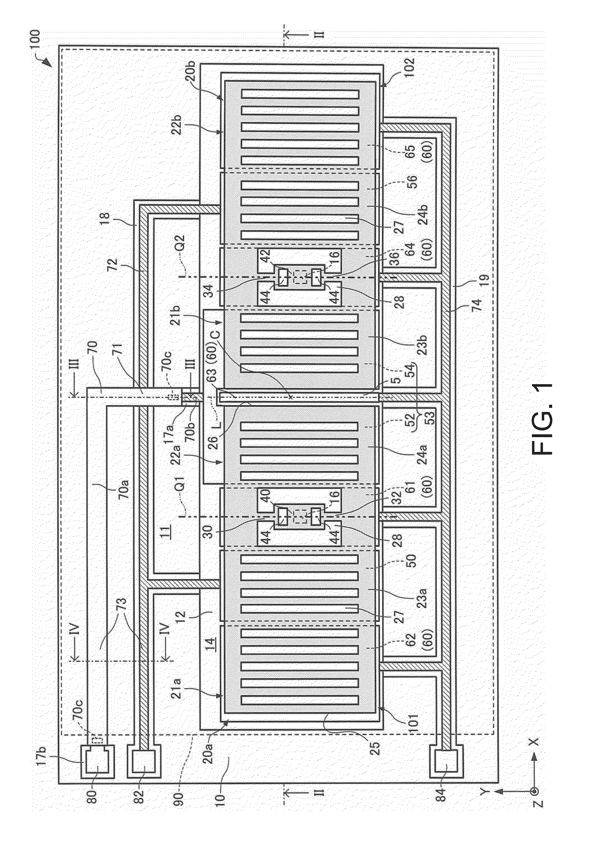
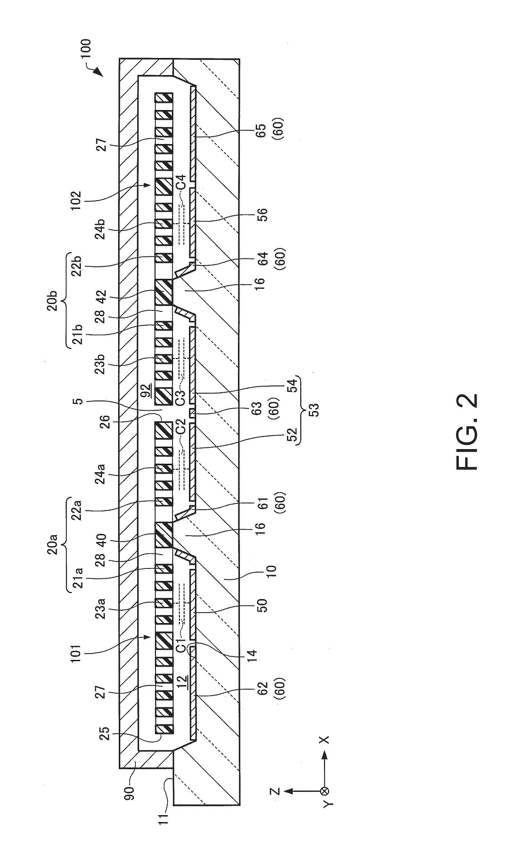
[0136]First, First Modification Example will be described. FIG. 8 is a plan view schematically showing the physical quantity sensor 200 according to First Modification Example. FIG. 9 is a cross-sectional view taken along line IX-IX of FIG. 8 and schematically showing the physical quantity sensor 200 according to First Modification Example. For convenience, the cover 90 is shown to be transparent in FIG. 8. In addition, in FIGS. 8 and 9 and FIGS. 10 to 13 which will be described below, the X axis, the Y axis, and the Z axis are shown as three axes which are orthogonal with respect to each other.

[0137]As shown in FIG. 8 and FIG. 9, in the physical quantity sensor 200, a groove portion 210 is formed on the substrate 10.

[0138]A plurality of the groove portions 210 are formed. The groove portions 210 are formed, in the substrate 10, in the area between the first fixed electrode portion 50 and the electrodes 60 adjacent to the first fixed electrode portion 50...

second modification example

2. Second Modification Example

[0144]Next, Second Modification Example will be described. FIG. 10 is a plan view schematically showing the physical quantity sensor 300 according to Second Modification Example. FIG. 11 is a cross-sectional view taken along line XI-XI of FIG. 10 and schematically showing the physical quantity sensor 300 according to Second Modification Example. For convenience, the cover 90 is shown to be transparent in FIG. 10.

[0145]As shown in FIG. 10 and FIG. 11, in the physical quantity sensor 300, protrusion portions 69 are provided on the fixed electrode portions 50, 52, 54, and 56 and the electrodes 60.

[0146]The protrusion portions 69 are protruded toward the upper portion (to the side of the first movable body 20a or the second movable body 20b) from the fixed electrode portions 50, 52, 54, and 56 and the electrodes 60. A shape of the protrusion portions 69 is a spindle shape, for example. The protrusion portions 69 are provided in the area overlapped with the ...


PUM


Abstract

A physical quantity sensor according to the embodiment includes: a substrate; a first movable body which is disposed on the substrate, can be displaced around a first support shaft, and includes a first movable electrode portion; a second movable body which is disposed on the substrate, can be displaced around a second support shaft, and includes a second movable electrode portion; and a fixed electrode portion which is overlapped on the first movable electrode portion and the second movable electrode portion and is disposed on the substrate in a plan view.

Description

CROSS-REFERENCE TO RELATED APPLICATIONS[0001]This application claims priority to Japanese Patent Application No. 2013-163001 filed on Aug. 6, 2013. The entire disclosure of Japanese Patent Application No. 2013-163001 is hereby incorporated herein by reference.BACKGROUND[0002]1. Technical Field[0003]The present invention relates to a physical quantity sensor, an electronic device, and a moving object.[0004]2. Related Art[0005]In recent years, a physical quantity sensor for detecting a physical quantity such as acceleration has been developed by using silicon micro electro mechanical systems (MEMS), for example.[0006]The physical quantity sensor, for example, includes a substrate, a fixed electrode portion fixed to the substrate, and a movable body including a movable electrode portion disposed to oppose the fixed electrode portion, and detects the physical quantity such as acceleration based on electrostatic capacitance between the movable electrode portion and the fixed electrode po...

Claims


Application Information

Patent Timeline
Patent Type & Authority Applications(United States)
IPC IPC(8): G01P15/125
CPCG01P15/125B81B3/0008B81B2201/0235B81B2201/0242B81B2207/012B81C2203/0109G01C19/5719G01P2015/0814
Inventor TANAKA, SATORU
Owner SEIKO EPSON CORP
Why Eureka
Try Eureka