Method and device for establishing a fault in connecting lines between a central unit and a plurality of electronic components which are independent of one another

a technology of electronic components and faults, applied in the direction of short-circuit testing, instrumentation, safeguarding apparatus, etc., can solve the problems of less comfort for the user of the vehicle, substantial time consumption before the vehicle may be put into operation, etc., and achieve the effect of reducing the complexity of cross-coupling testing controlled via software and high time requirements

Active Publication Date: 2016-02-11
ROBERT BOSCH GMBH
View PDF0 Cites 0 Cited by
  • Summary
  • Abstract
  • Description
  • Claims
  • Application Information

AI Technical Summary

Benefits of technology

[0010]Furthermore, the present invention provides a device which is designed to carry out or implement the steps of the method according to the present invention or a variant thereof in corresponding apparatuses. The object on which the present invention is based may also be achieved rapidly and efficiently by this embodiment variant of the present invention in the form of a device.
[0021]To allow particularly rapid storage of the fault values in the affected components or particularly rapid readout of the ascertained fault values by the control unit of the central unit, according to one special specific embodiment of the present invention, in the step of registering, storing of the fault value in the first register may be carried out, the first register being a part of the second connection unit or the first register being a part of the control unit of the central unit.

Problems solved by technology

However, this is very time-consuming, since the control of the test via software requires a substantial number of commands to be read out and executed.
In particular in automotive technology, in which all safety-relevant systems must be thoroughly tested before beginning travel, in future vehicles having a large number of sensors connected to one another as components, this may mean substantial time consumption before the vehicle may be put into operation.
This is less comfortable for a user of the vehicle.

Method used


Image

  • Method and device for establishing a fault in connecting lines between a central unit and a plurality of electronic components which are independent of one another
  • Method and device for establishing a fault in connecting lines between a central unit and a plurality of electronic components which are independent of one another
  • Method and device for establishing a fault in connecting lines between a central unit and a plurality of electronic components which are independent of one another

Examples


Embodiment Construction

[0028]In the following description of preferred exemplary embodiments of the present invention, identical or similar reference numerals are used for the similarly acting elements shown in the various figures, a repeated description of these elements being omitted.

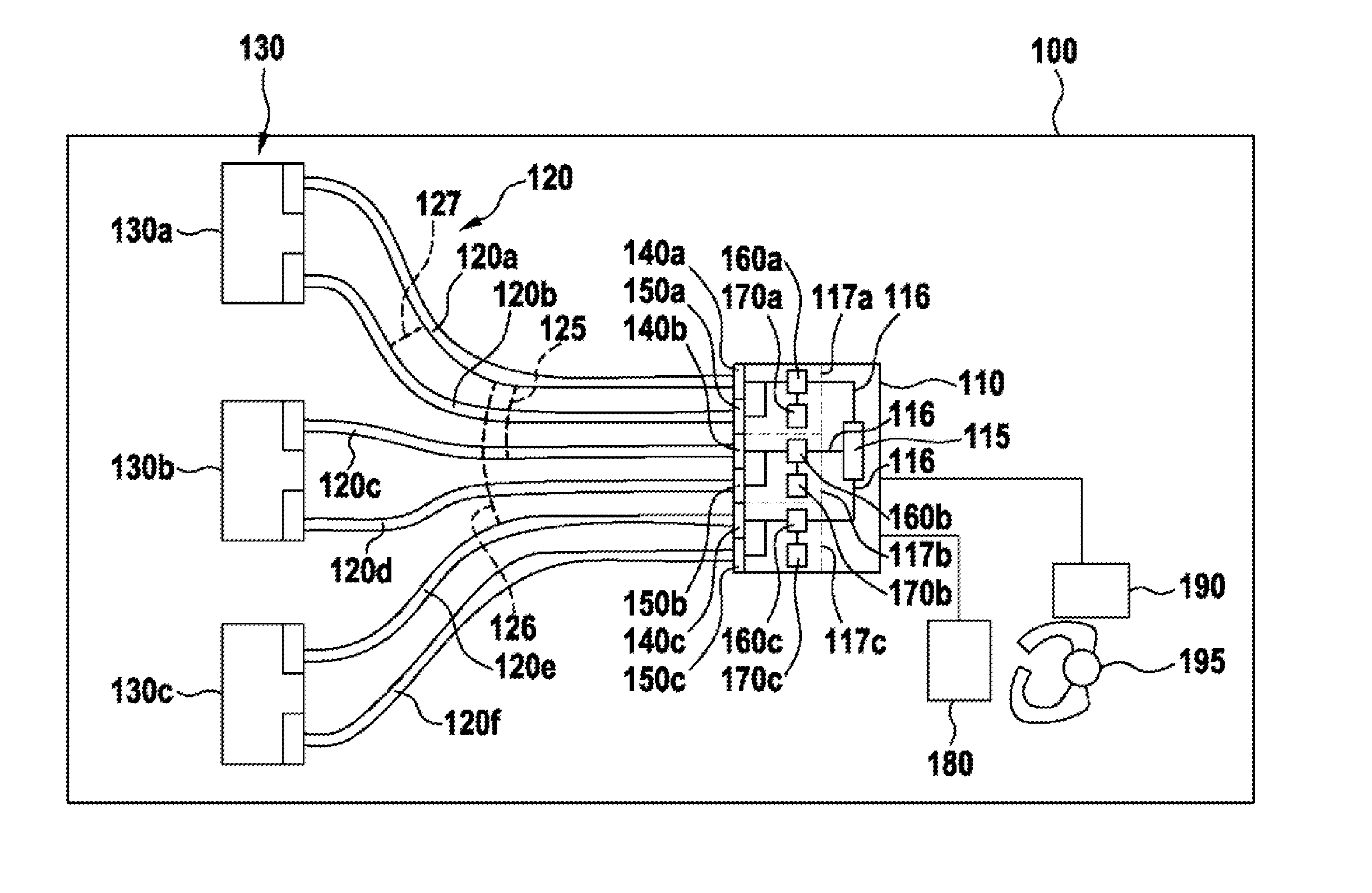
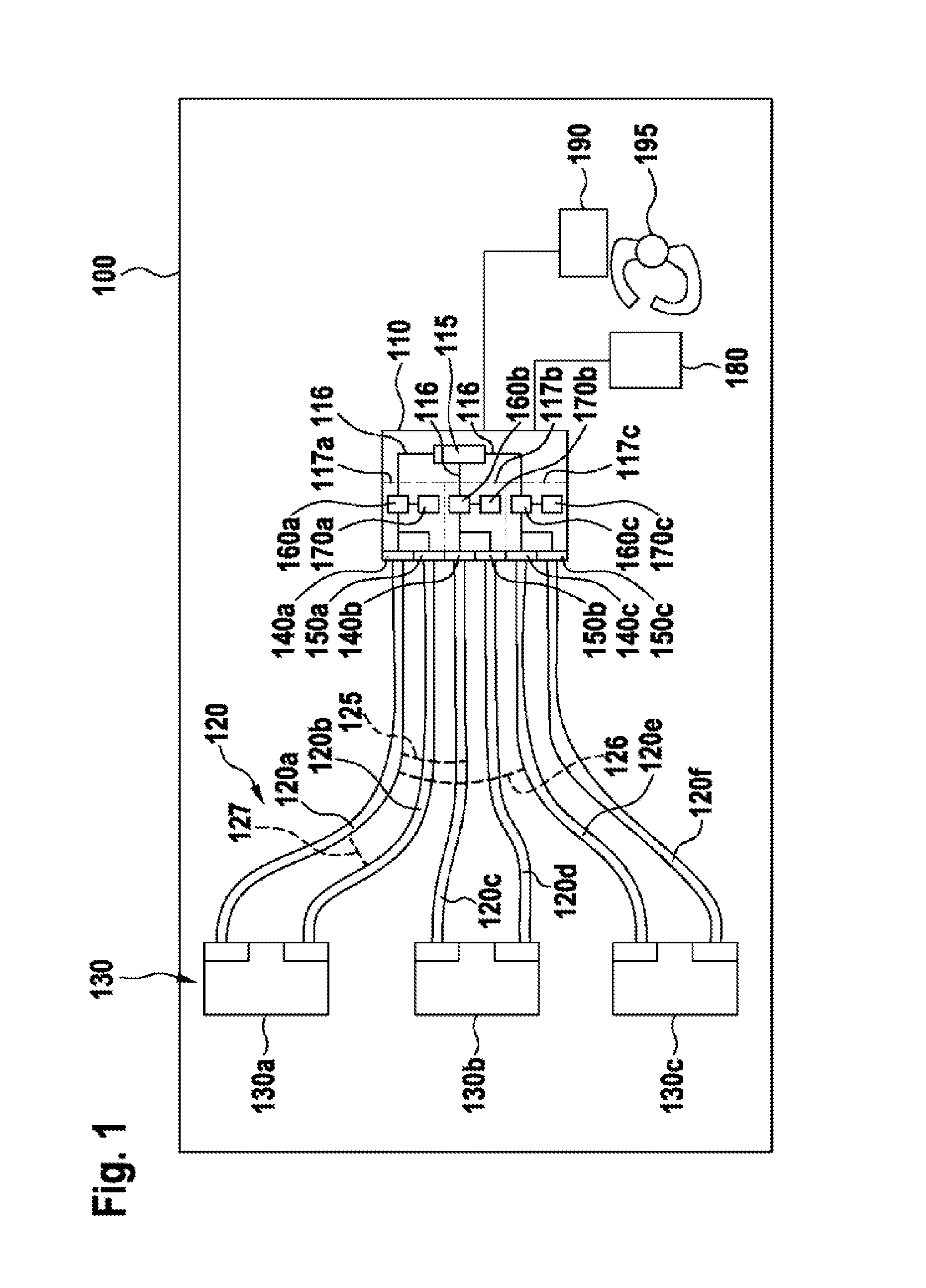
[0029]FIG. 1 shows a block diagram of a vehicle 100, in which an exemplary embodiment of the present invention is used. A software-controlled central unit 110 is provided in this case. Central unit 110 includes a control unit 115, which is designed, for example, as a microcontroller or digital signal processor and which is connected via an SPI bus 116 to connection units 117, for example, which are provided as a hardware interface for contacting external units (described in greater detail hereafter). Connection units 117 are connected via connecting lines 120, which are each implemented as two-wire signal lines (for example, in the form of a PSI5 connecting line or interface), to interfaces of a plurality of peripheral unit...


PUM


Abstract

A method for establishing at least one fault in connecting lines between electronic connection units and peripheral units, which are independent of one another, includes: outputting a start signal from the control unit to a first of the connection units, to start the establishment of the fault; applying a test signal to an interface of a first one of the connection units, the application of the test signal being monitored and / or controlled by a non-volatile first algorithm of the first connection unit; registering a cross-coupling of the test signal to an interface of a second connection unit and storing a fault value representing the cross-coupling in a first register, the registration and the storage of the fault value being monitored and / or controlled by a nonvolatile second algorithm of the second connection unit.

Description

BACKGROUND OF THE INVENTION[0001]1. Field of the Invention[0002]The present invention relates to a method for establishing a fault in connecting lines between a central unit and a plurality of electronic components which are independent of one another, to a corresponding device, and to a corresponding computer program product.[0003]2. Description of the Related Art[0004]A cross-coupling test between PSI5 interfaces of one or more ASICs on a circuit board has previously been carried out via software control. However, this is very time-consuming, since the control of the test via software requires a substantial number of commands to be read out and executed. In particular in automotive technology, in which all safety-relevant systems must be thoroughly tested before beginning travel, in future vehicles having a large number of sensors connected to one another as components, this may mean substantial time consumption before the vehicle may be put into operation. This is less comfortabl...

Claims


Application Information

Patent Timeline
Patent Type & Authority Applications(United States)
IPC IPC(8): G01R31/00G01R31/58
CPCG01R31/007G01R31/025G01D3/08G01R31/52G01R31/58
Inventor WEISS, TIMOSIEMSS, MATTHIASWIDMAIER, JOCHENWEISS, GUENTER
Owner ROBERT BOSCH GMBH
Why Eureka
Try Eureka