
Multidirectional electrical connector, plug and system

a multi-directional, plug-in technology, applied in the direction of coupling device connection, coupling contact member, two-part coupling device, etc., can solve the problems of slow adoption of all-electric vehicles by large populations, relatively long time-consuming and laborious, and high cost, especially the cost of secondary batteries

Active Publication Date: 2016-02-11
GOGORO
View PDF5 Cites 16 Cited by
  • Summary
  • Abstract
  • Description
  • Claims
  • Application Information

AI Technical Summary

Benefits of technology

The patent text describes a solution for using electrical connectors to connect portable battery devices to devices that need power or to charging devices for the batteries. These connectors can make electrical connections in multiple orientations, which allows for safer and more robust connections. This improves the quality of the air and the health of populations by reducing emissions from combustion engines. The technical effects of the patent text include improved safety and reliability of the electrical connectors and more widespread use of portable battery devices.

Problems solved by technology

While the zero tail pipe emissions benefit of all-electric vehicles are appreciated, adoption of all-electric vehicles by large populations has been slow.
One of the reasons appears to be the cost, particularly the cost of secondary batteries.
Another one of the reasons appears to be the limited driving range available on a single charge of a battery, and the relatively long time (e.g., multiple hours) necessary to recharge a secondary battery when depleted.
Yet another reason appears to be the complicated nature of replacing secondary batteries in all-electric vehicles.
Conventional electrical connectors like cigarette lighter style electrical connectors include a positive pin in the form of a spring and point contact which are not designed to safely handle currents much greater than 20 amps or applications involving high levels of vibration.

Method used


Image

  • Multidirectional electrical connector, plug and system
  • Multidirectional electrical connector, plug and system
  • Multidirectional electrical connector, plug and system

Examples


Embodiment Construction

[0073]It will be appreciated that, although specific embodiments of the present disclosure are described herein for purposes of illustration, various modifications may be made without departing from the spirit and scope of the present disclosure. Accordingly, the present disclosure is not limited except as by the appended claims.

[0074]In the following description, certain specific details are set forth in order to provide a thorough understanding of various disclosed embodiments. However, one skilled in the relevant art will recognize that embodiments may be practiced without one or more of these specific details, or with other methods, components, materials, etc. In other instances, well-known structures associated with portable electrical energy storage devices, batteries, super- or ultra-capacitors, electrical terminals, devices to be powered by portable electrical energy storage devices, devices for charging portable electrical energy storage devices and electrical connectors fo...


PUM


Abstract

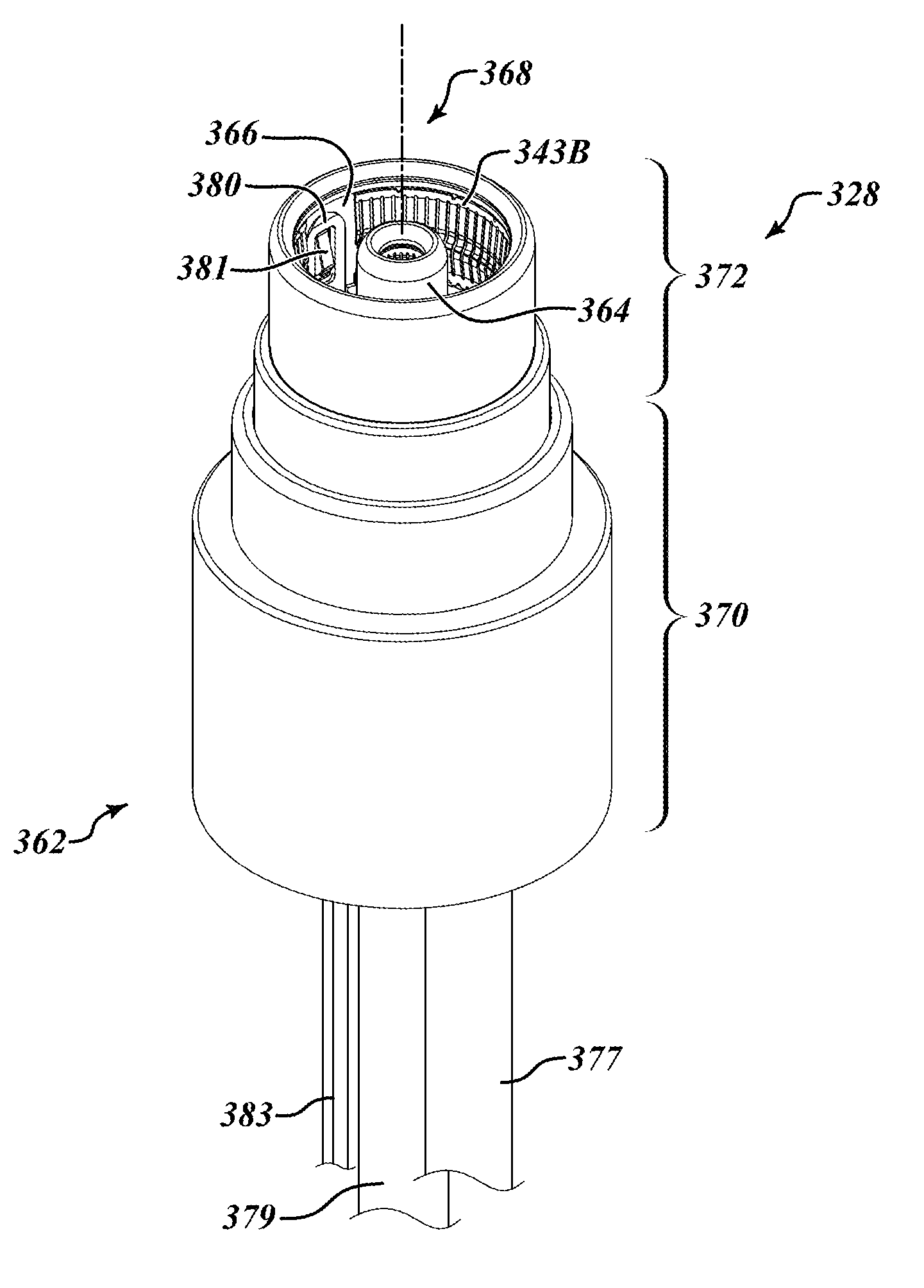
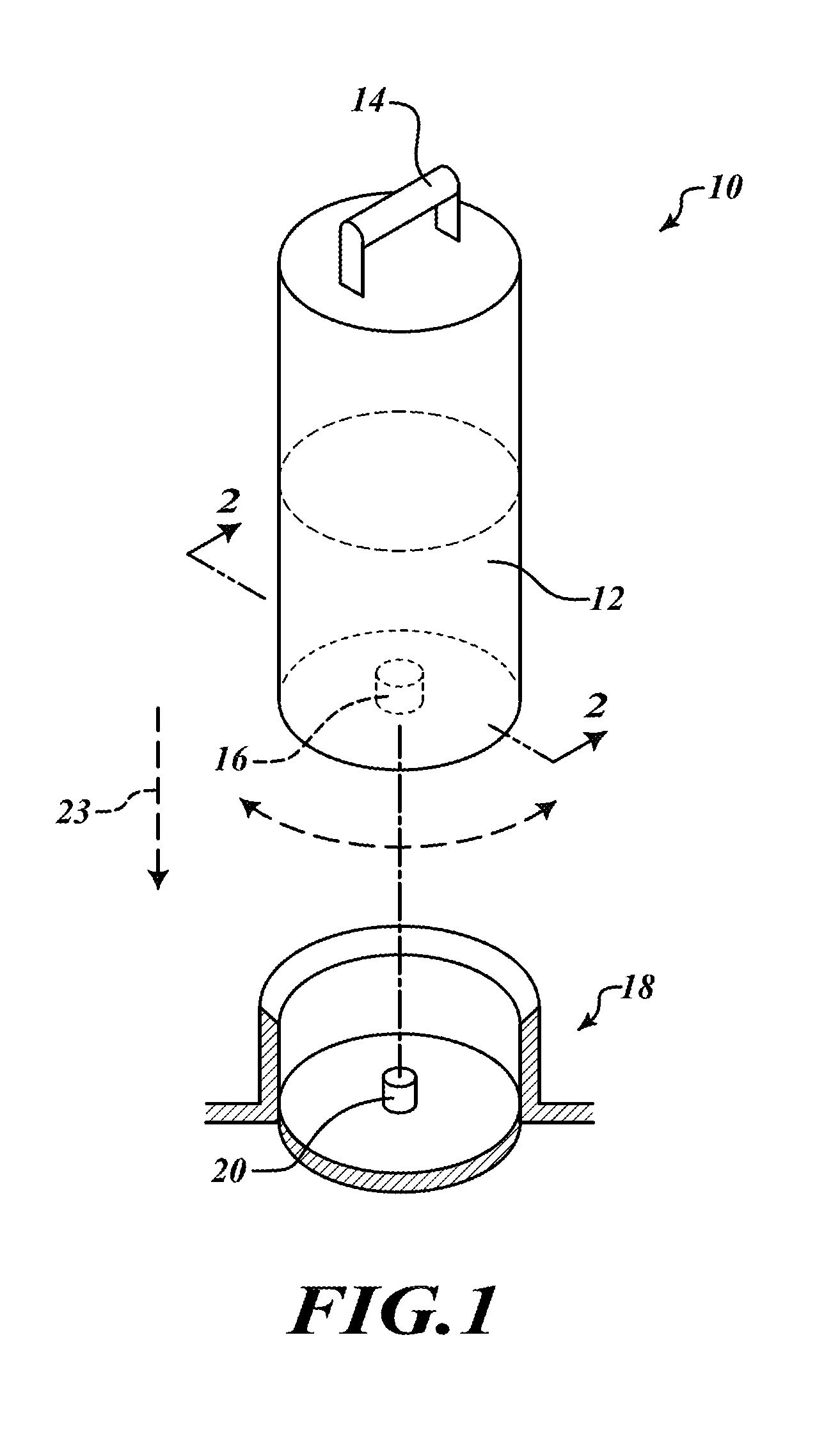
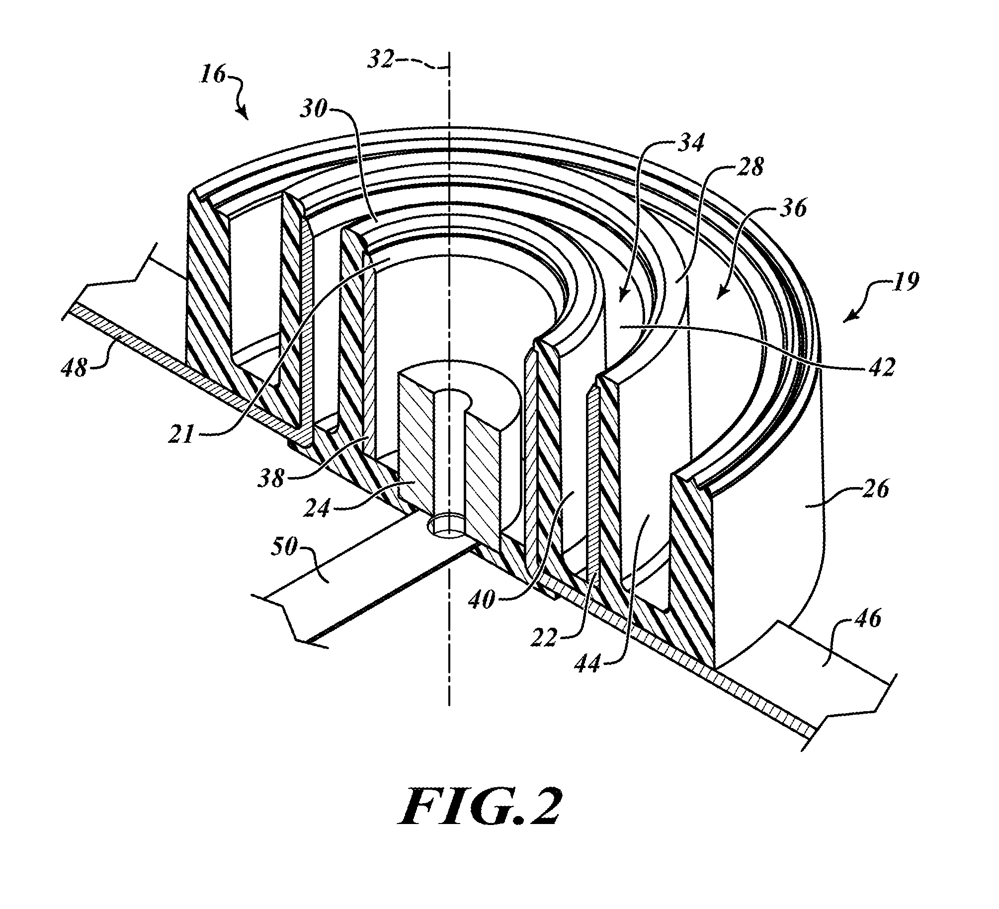
Multidirectional electrical connectors, electrical connector plugs and electrical connection systems for electrically connecting a portable energy storage device to an electrically powered device, such as an electric powered vehicle or a device for electrically charging the portable electrical energy storage device are described. The multidirectional feature of the electrical connectors, electrical connector plugs and electrical connections systems permit electrical connection between the electrical connectors and electrical connector plugs in a plurality of rotational orientations between a portable electrical energy storage device to which a connector or plug is electrically connected and an electrically powered device to which a corresponding plug or connecter is electrically connected.

Description

BACKGROUND[0001]1. Technical Field[0002]The embodiments described herein relate to portable electrical energy storage devices, such as those used to power electric powered devices such as vehicles and consumer electronics, and connectors for making an electrical connection between such portable electrical energy storage devices and devices to be powered by or used to charge such portable electrical energy storage devices.[0003]2. Description of the Related Art[0004]Batteries such as lithium-ion batteries are known for storing more energy into smaller, lighter units. Lithium-ion batteries have found wide application in powering portable electronic devices such as cell phones, tablets, laptops, power tools and other high-current equipment. The low weight and high energy density also makes lithium-ion batteries attractive for use in hybrid electric vehicles and fully electric-powered vehicles.[0005]In some applications, a plurality of individual lithium-ion batteries are packaged toget...

Claims


Application Information

Patent Timeline
Patent Type & Authority Applications(United States)
IPC IPC(8): H01R13/642
CPCH01R13/642H01R24/38H01R24/58H01R35/02H01R35/04H01R13/187H01R13/641H01R13/11
Inventor WU, YI-TSUNGLIN, SUNG-CHINGHSU, CHEN-SHINCHEN, YU-MIN
Owner GOGORO
Learn More