Charge and discharge device, charge and discharge control method, and program

a technology of charge and discharge device and control method, which is applied in the direction of secondary cell servicing/maintenance, electrochemical generator, transportation and packaging, etc., can solve the problem of insufficient uniform voltage of the entire battery cell, and achieve the effect of high accuracy

Inactive Publication Date: 2016-02-11
NEC CORP
View PDF12 Cites 15 Cited by
  • Summary
  • Abstract
  • Description
  • Claims
  • Application Information

AI Technical Summary

Benefits of technology

[0010]According to the invention, it is possible to uniformize voltages of plural battery cells that are connected in series with high accuracy.

Problems solved by technology

However, in the charge state control device disclosed in Patent Document 1, there is a concern that the uniformization of voltages of the entirety of the battery cells is insufficient.

Method used


Image

  • Charge and discharge device, charge and discharge control method, and program
  • Charge and discharge device, charge and discharge control method, and program
  • Charge and discharge device, charge and discharge control method, and program

Examples


first exemplary embodiment

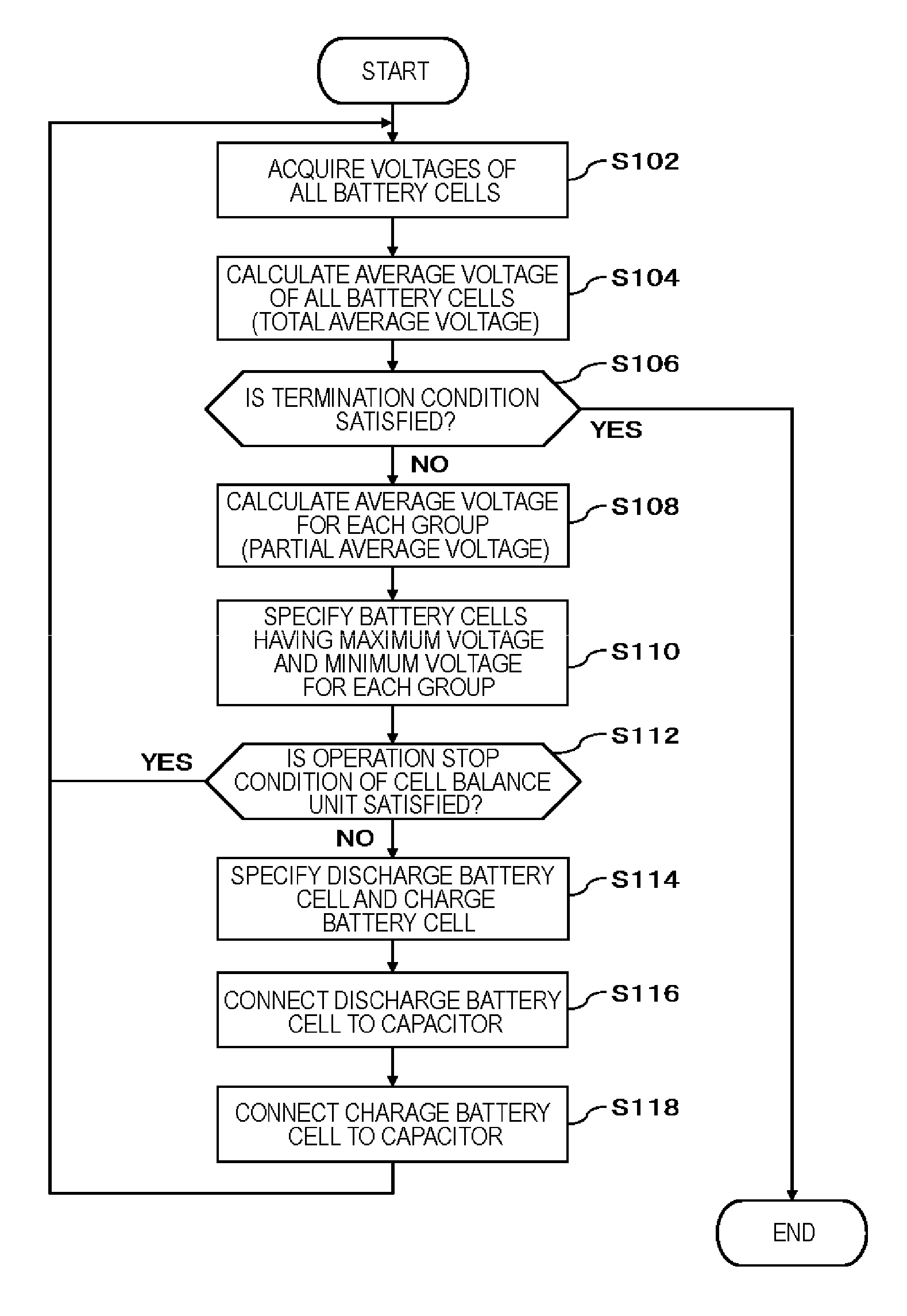
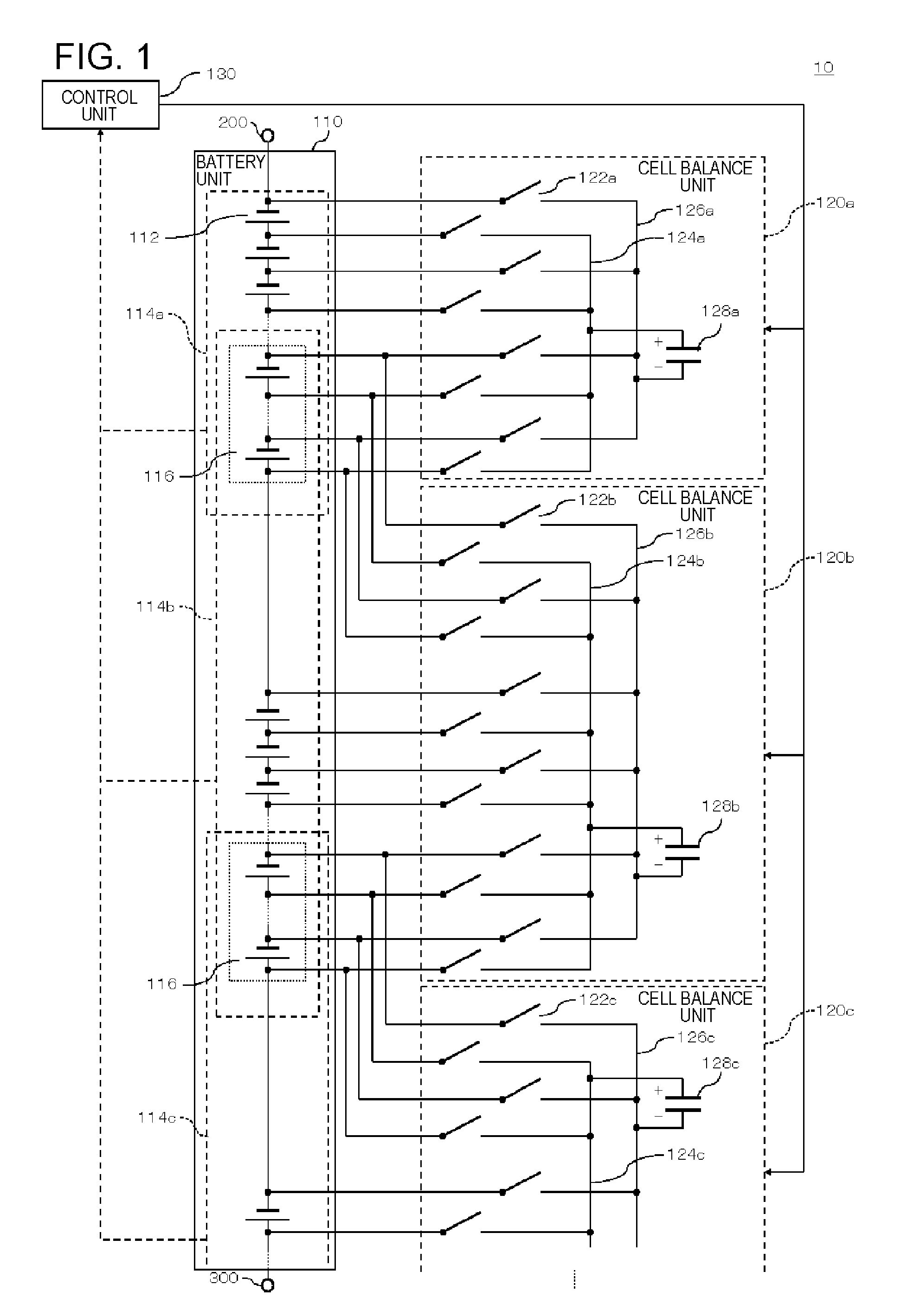
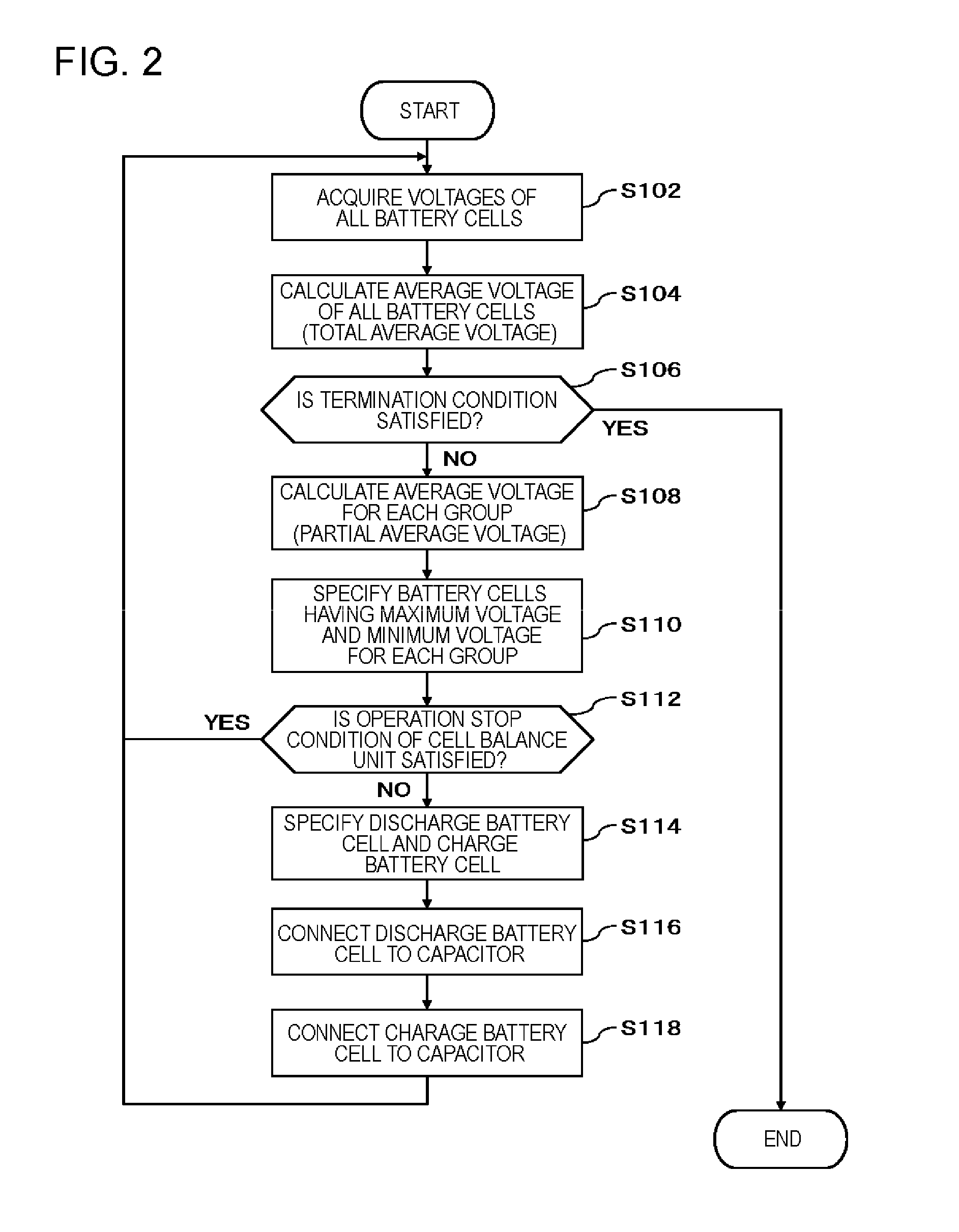
[0018]FIG. 1 is a diagram illustrating a processing configuration example of a charge and discharge device 10 according to a first exemplary embodiment. In FIG. 1, the charge and discharge device 10 includes a battery unit 110, a cell balance unit 120, and a control unit 130.

[0019]The battery unit 110 includes m (m is an integer of 3 or more) battery cells 112 that are connected in series. The m battery cells 112 are grouped into plural groups 114 (114a to 114c in FIG. 1) configured of n (n is an integer equal to or larger than 2 and smaller than m) battery cells 112 that are continuously arranged. Further, as shown in FIG. 1, a part of the battery cells 112 that belong to a certain group 114 is shared by a different group 114. Hereinafter, the above-described shared battery cell 112 is referred to as a common battery cell 116. The number and position of the common battery cells 116 are not limited to the example shown in FIG. 1. Further, the battery unit 110 is a lithium ion batter...

second exemplary embodiment

[0041]The present exemplary embodiment is the same as the first exemplary embodiment, except for the following points.

[0042]FIG. 5 is a diagram illustrating a configuration of the control unit 130 in the second exemplary embodiment. The control unit 130 in the present exemplary embodiment further includes a correction unit 132.

[0043]The correction unit 132 corrects a numerical value of the total average voltage Vall calculated by the control unit 130 using a correction value α. Further, the control unit 130 determines the specific condition described in the first exemplary embodiment using the numerical value of the total average voltage Vall corrected by the correction unit 132. The correction value α will be described hereinafter. In the following description, it is assumed that the voltage of the battery cell 112 increases or decreases in proportion to the capacity of the battery cell 112.

[0044]First, before and after a first cell balance operation is executed, the total average ...


PUM

PropertyMeasurementUnit
voltagesaaaaaaaaaa
voltageaaaaaaaaaa
average voltageaaaaaaaaaa

Abstract

A charge and discharge device (10) includes: a battery unit (110) in which m (m is an integer of 3 or more) battery cells (112) that are connected in series are grouped into plural groups (114) including n (n is an integer equal to or larger than 2 and smaller than m) battery cells (112) that are continuously arranged and a part of the battery cells (112) that belong to a certain group is shared by a different group; a cell balance unit (120) that is provided for each group (114) and uniformizes voltages of the battery cells (112) that belong to the group (114); and a control unit (130) that stops the operation of the cell balance unit (120), when a voltage difference of the battery cells (112) that belong to an arbitrary one of the groups (114) is within a predetermined value, and when a total average voltage in all the battery cells (112) and a partial average voltage which is an average voltage of the battery cells (112) that belong to the arbitrary group (114) satisfy a specific condition, the cell balance unit (120) corresponding to the arbitrary group (114).

Description

TECHNICAL FIELD[0001]The present invention relates to a charge and discharge device, a charge and discharge control method, and a program capable of uniformizing voltages (capacities) of plural battery cells that are connected in series.BACKGROUND ART[0002]In use of plural battery cells that are connected in series, variation in voltages (capacities) thereof occurs according to a characteristic of each battery cell, a use environment, or the like. The variation of the voltages may cause over-charge or over-discharge. Further, when plural battery cells that are connected in series are used, charging is stopped at a voltage such that a battery cell that has the highest voltage is not over-charged during charging, and discharging is stopped at a voltage such that a battery cell that has the lowest voltage is not over-discharged during discharging. Thus, a use range of the entire series voltages becomes limited, and thus, usable capacities of the battery cells are reduced.[0003]As an ex...

Claims


Application Information

Patent Timeline
Patent Type & Authority Applications(United States)
IPC IPC(8): H02J7/00H01M10/44H01M10/48
CPCH02J7/0016H01M10/441H01M2010/4271H02J7/0021H01M10/482H02J7/0019H02J7/345H02J7/0014Y02E60/10H02J7/0048Y02T10/70
Inventor MIYAMOTO, JUNICHITAKAHASHI, SHINGOLUO, YUANNOSHIDA, NOBUHIDE
Owner NEC CORP
Why Eureka
Try Eureka