Neutral Ring for Use in Rotating Electrical Machine and Method for Manufacturing the Same

a technology of rotating electrical machines and neutron rings, which is applied in the direction of applying solid insulation, dynamo-electric machines, electrical apparatus, etc., can solve the problems of accumulating junction fatigue damage, and achieve the effects of reducing stress, preventing fatigue damage, and less rigidity

Active Publication Date: 2016-02-11
HITACHI IND PROD LTD
View PDF3 Cites 16 Cited by
  • Summary
  • Abstract
  • Description
  • Claims
  • Application Information

AI Technical Summary

Benefits of technology

[0010]In an aspect of the invention, the present invention provides a neutral ring that reduces stress due to the deformation difference and prevents fatigue damage from being accumulated and a method of manufacturing the neutral ring in which a related neutral ring can be altered to the neutral ring of the present invention.
[0011]To solve the problem mentioned above, in the present invention, a neutral ring is not a rigid body in a ring shape but is formed with a plurality of arc-shaped members that are connected with one another to have a flexible structure so as to follow deformation of a coil. The neutral ring of the present invention is formed with the plurality of arc-shaped members that are connected with one another being overlapped in a circumferential direction to have less rigidity as compared with the ring shape.
[0012]Since the neutral ring having low rigidity can easily follow deformation of the coils due to centrifugal force, the junctions between the coils and the neutral ring do not receive large stress. As a result, the fatigue damage on the neutral ring can be reduced to allow for extending the service life of the neutral ring.

Problems solved by technology

When a deformation difference between the neutral ring and the coils due to centrifugal force caused by rotation of the rotor increases, the stress at the junctions between the neutral ring and the coils becomes larger, to cause fatigue damage to be accumulated in the junctions.

Method used


Image

  • Neutral Ring for Use in Rotating Electrical Machine and Method for Manufacturing the Same
  • Neutral Ring for Use in Rotating Electrical Machine and Method for Manufacturing the Same
  • Neutral Ring for Use in Rotating Electrical Machine and Method for Manufacturing the Same

Examples


Embodiment Construction

[0020]An embodiment of the present invention will be described with reference to FIGS. 1 to 5.

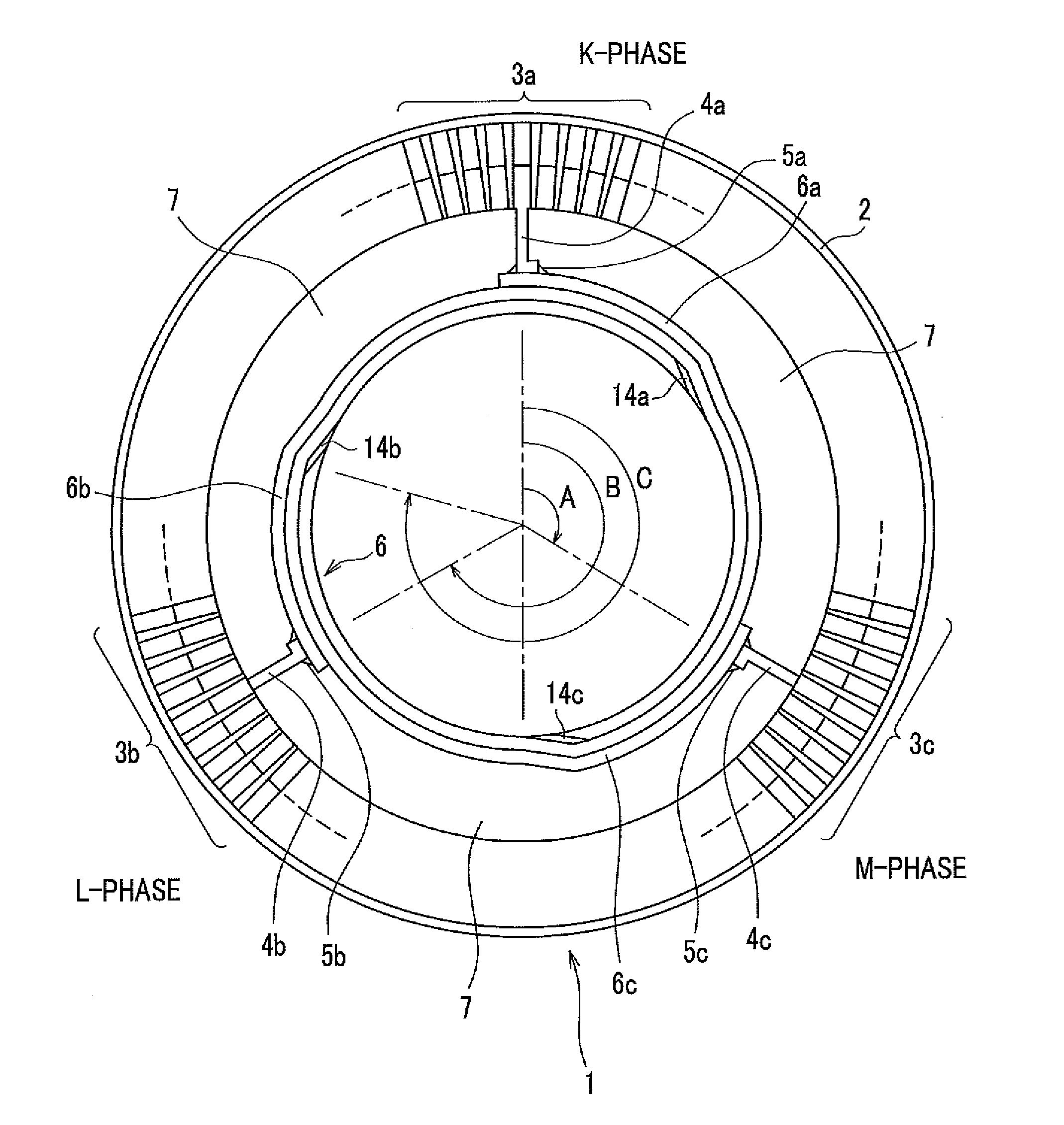
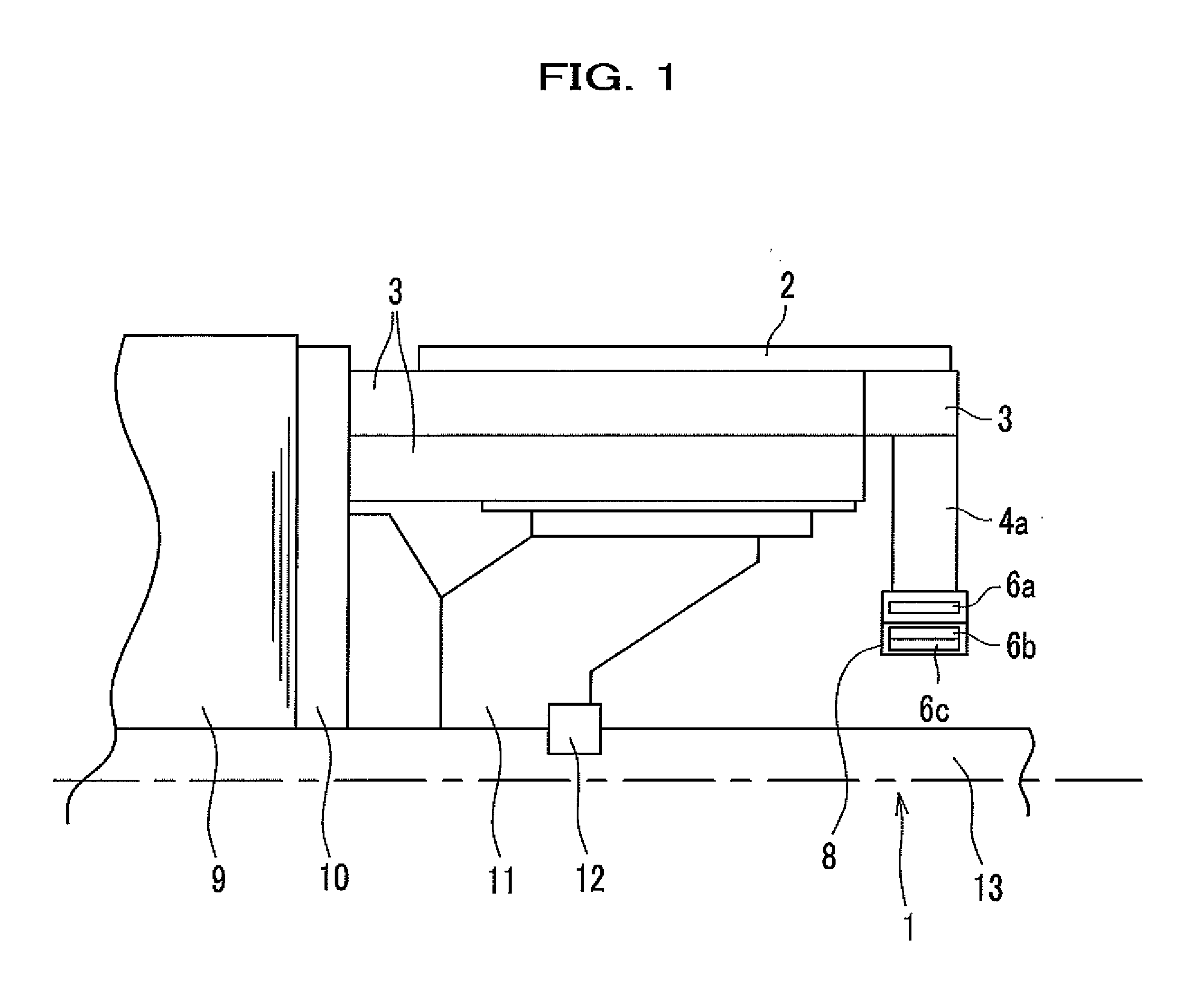
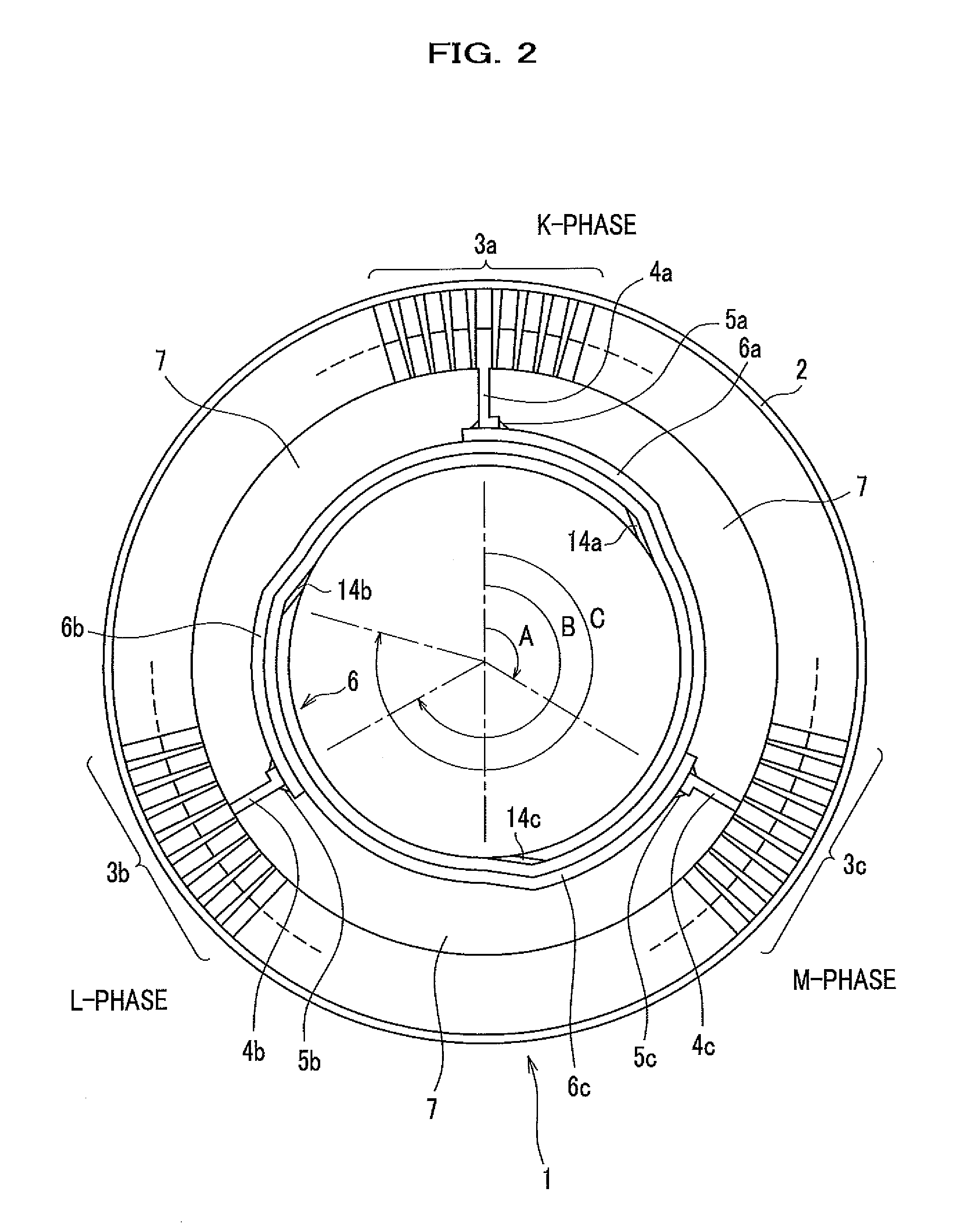
[0021]FIG. 1 is a partial cross sectional view in which an upper half of a rotor 1 in a rotating electrical machine is cut out in an axis direction to show a main part of the present invention. FIG. 2 is a cross sectional view as viewed from the axis direction to show the main part of the rotor 1.

[0022]The rotor 1 includes: a rotor core 9; a core back 10 that fixes the rotor core 9 to a rotor shaft 13; a rotor clamp 11; a key 12; a coil 3 including a K-phase coil 3a, an L-phase coil 3b, an M-phase coil 3c that penetrates into the rotor core 9; a bind 2 that receives centrifugal force of the coil 3; and a K-phase lead-out wire 4a, an L-phase lead-out wire 4b, an M-phase lead-out wire 4c that are connected to the coil 3 (one end of each lead-out wire is connected to the coil 3 and the other end thereof is connected to a neutral ring 6 including neutral ring members 6a, 6b and 6c, to connect t...


PUM

PropertyMeasurementUnit
centrifugal forceaaaaaaaaaa
rotationaaaaaaaaaa
electrical propertyaaaaaaaaaa

Abstract

A rotating electrical machine includes a rotor core, a rotor shaft, a coil, a bind, a lead-out wire of which one end is connected to the coil and the other end is connected to a neutral ring. A filling is filled between the coil and the neutral ring. The neutral ring is formed with a plurality of members that are connected with one another to have flexibility.

Description

CROSS REFERENCE TO RELATED APPLICATION[0001]This application claims the benefit of priority to Japanese Patent Application No. 2014-162022, filed on Aug. 8, 2014, the entire specification, claims and drawings of which are hereby incorporated by reference.BACKGROUND OF THE INVENTION[0002]1. Field of the Invention[0003]The present invention relates to a neutral point (neutral ring) for use in a rotor of a rotating electrical machine and a method for manufacturing the same.[0004]2. Description of the Related Arts[0005]Field coils of a rotor of a rotating electrical machine using three-phase AC are arranged with a neutral point called as a neutral ring for shunting respective phase coils. In general, the neutral ring is a ring-shaped member made of metal such as copper and an aluminum alloy having a favorable electrical property of a resistance or the like, and connected to one ends of respective phase coils to constitute a star connection of three-phase coils.[0006]When the rotor rotat...

Claims


Application Information

Patent Timeline
Patent Type & Authority Applications(United States)
IPC IPC(8): H02K3/28H02K15/00H02K15/10
CPCH02K3/28H02K15/0062H02K15/10H02K3/51H02K13/003Y10T29/49012
Inventor HAYASAKA, YASUSHIMATSUMOTO, MASANORIOTSUKI, YASUNORIFUJIGAKI, TETSUOYASUI, YOSHIHIROIIZUKA, MOTONOBUENDOU, MASAAKIFUKUNAGA, ATSUSHINAKAYAMA, TAKESHI
Owner HITACHI IND PROD LTD
Why Eureka
Try Eureka