Al technical title is built by PatSnap Al team. It summarizes the technical point description of the patent document.
a retractor and rotor body technology, applied in the field of medical devices, to achieve the effect of reducing material costs, less strength and rotor back force, and maintaining rigidity and rotor back
Inactive Publication Date: 2016-02-18
APPL MEDICAL RESOURCES CORP
View PDF3 Cites 2 Cited by
Summary
Abstract
Description
Claims
Application Information
AI Technical Summary
This helps you quickly interpret patents by identifying the three key elements:
Problems solved by technology
Method used
Benefits of technology
[0009]A wound retractor incorporating an inner ring manufactured using extrusion techniques with reduced material costs yet still maintaining the rigidity and bounce back of a fully dense injection-molded ring is described. Although a ring with void spaces or lumens generally has less strength and bounce-back force than a fully dense molded ring, it was surprisingly discovered that a ring could be fashioned by more cost effective extrusion techniques, providing a substantial reduction in material costs, while maintaining the superior features of the fully dense ring, provided a stable internal wall structure is maintained within the ring cross-section. Moreover, it was determined that such rings provide the same performance as fully dense rings when incorporated into wound retractors.
[0010]The inventive, more cost-effective wound retractor comprises a longitudinal axis defining an instrument access channel extending from a proximal end to a distal end, an outer ring, an inner ring, wherein the inner ring has a teardrop-shaped cross section, a first lumen, a second lumen, and a stable internal wall structure separating the first lumen from the second lumen, and a flexible, tubular sheath extending between the outer ring and the inner ring. In some embodiments, the outer ring comprises an annular axis around which the outer ring is rotatable. Optionally, the outer ring includes surfaces that are easy to grip and turn, allowing the user to roll the flexible ring over itself to provide the sheath with a radial retraction force sufficient to stretch an incision to a desired diameter. In some embodiments, the outer ring may be rolled over itself to provide the sheath with a radial retraction force sufficient to seal the sheath against the edges of a wound incision.
Problems solved by technology
This manufacturing process allows for material reduction, by introducing lumen(s) for example, thereby saving costs, but may produce unsatisfactory results when used in a wound retractor.
Method used
Image
Click on the blue label to locate the original text in one second.
Reading with bidirectional positioning of images and text.
Examples
Embodiment Construction
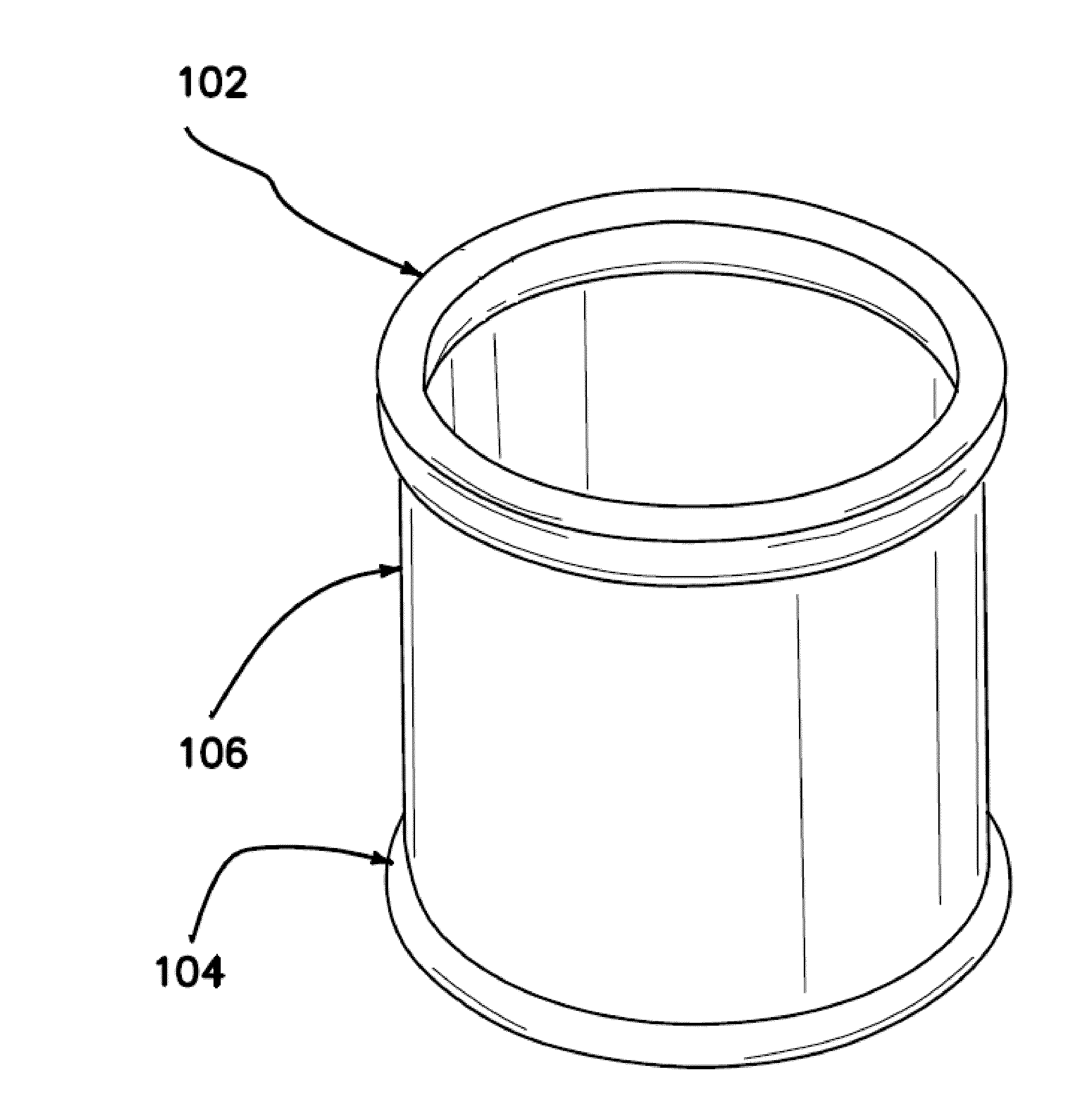
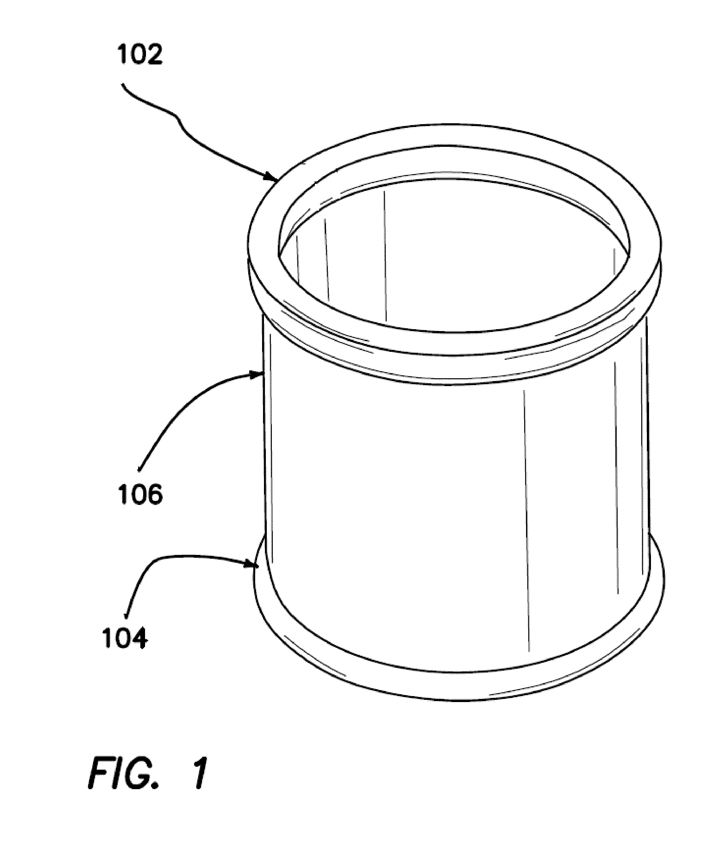
[0024]FIG. 1 illustrates an adjustable wound retractor 100 useful in a variety of surgical procedures. The wound retractor 100 includes an outer ring 102, an inner ring 104, and a distensible sleeve 106 coupling the outer ring and the inner ring. Outer ring 102 is shown as a single ring, but may also be a double ring or triple ring or multiples thereof.
[0025]The sleeve 106 may be coupled to the outer ring 102 and the inner ring 104 by heat seal, adhesive, or other means that are well known in the art. The sleeve 106 may be made of a material that is flexible and impermeable to fluids and bacteria.
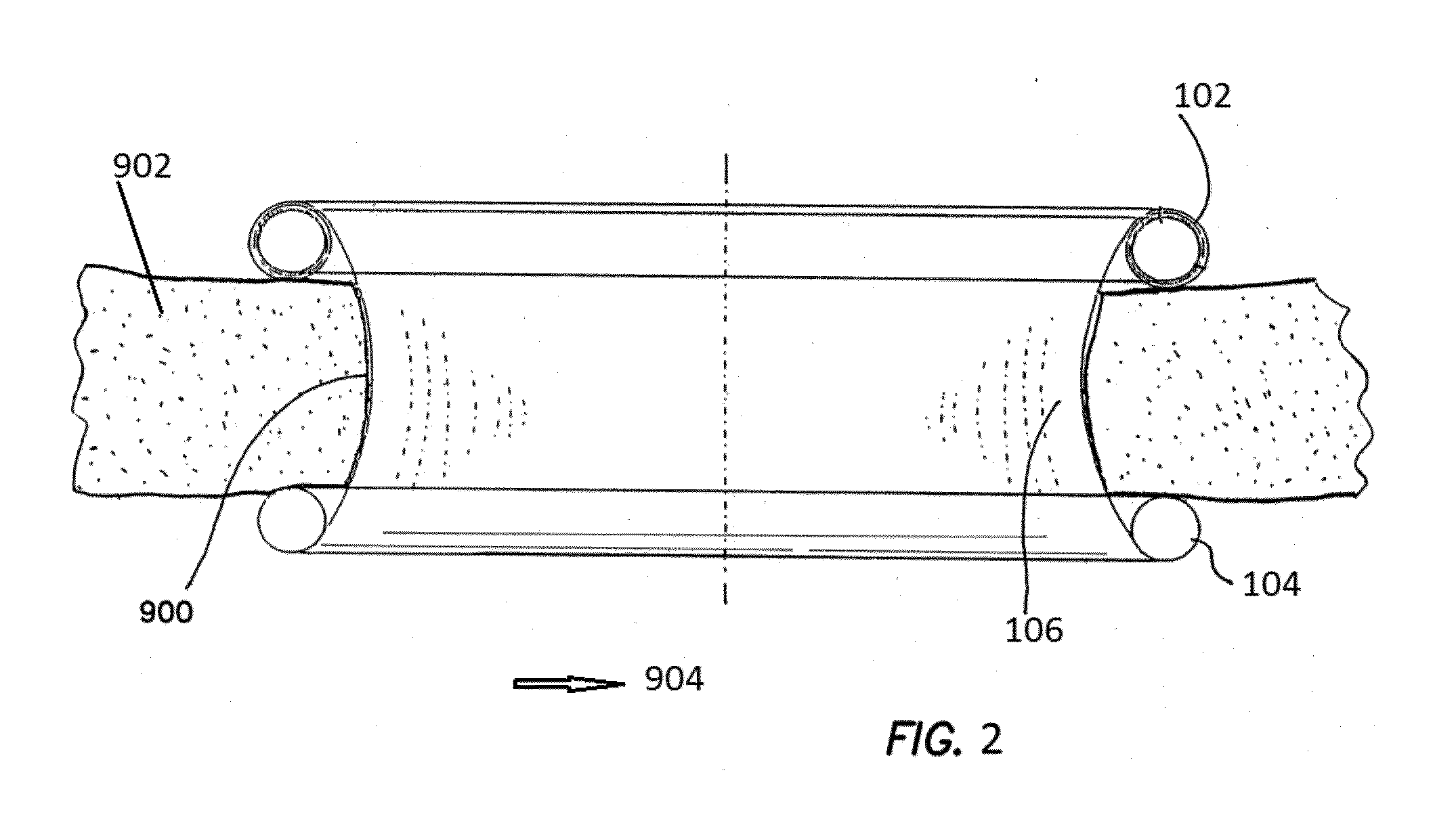
[0026]The inner ring 104 may be made of materials of sufficient hardness to retain its shape after insertion into a body cavity 904 (FIG. 2) but sufficiently flexible so as to allow the inner ring to be compressed for insertion through an incision. The materials of which the outer ring 102 is made must allow the outer ring to be turned around its annular axis as further described below. The...
PUM
Property
Measurement
Unit
thickness
aaaaa
aaaaa
flexible
aaaaa
aaaaa
diameter
aaaaa
aaaaa
Abstract
A wound retractor comprising an outer ring, an inner ring, and a flexible sheath extending therebetween is described, wherein the inner ring has the strength, rigidity and bounce back characteristics of a solid injection-molded ring yet is manufactured by extrusion techniques described herein with a 20-30% reduction in materials, resulting in reduced manufacturing costs.
Description
CROSS REFERENCE TO RELATED APPLICATIONS[0001]This application claims the benefit of U.S. Application No. 62 / 037,501, filed Aug. 14, 2014, the entire disclosure of which is incorporated by reference.BACKGROUND[0002]1. Field[0003]This invention generally relates to medical devices and, more specifically, to a wound retractor having an improved inner ring.[0004]2. Discussion of the Related Art[0005]Wound retractors / protectors have been described in U.S. Pat. Nos. 7,650,887; 7,727,146; 7,883,461; 7,913,697; 8,235,054, and 8,267,858, the disclosures of which are hereby incorporated by reference in their entireties. The basic components of such wound retractors include an outer ring or rings, which may be flexible or rigid, an inner ring, and flexible sleeve attached at either end to the outer and inner ring.[0006]In use, the inner ring of the wound retractor is compressed for insertion through an incision. Once placed, the inner ring requires a particular “bounce back” force to ensure th...
Claims
Application Information
Patent Timeline
Application Date:The date an application was filed.
Publication Date:The date a patent or application was officially published.
First Publication Date:The earliest publication date of a patent with the same application number.
Issue Date:Publication date of the patent grant document.
PCT Entry Date:The Entry date of PCT National Phase.
Estimated Expiry Date:The statutory expiry date of a patent right according to the Patent Law, and it is the longest term of protection that the patent right can achieve without the termination of the patent right due to other reasons(Term extension factor has been taken into account ).
Invalid Date:Actual expiry date is based on effective date or publication date of legal transaction data of invalid patent.
Patent Type & Authority Applications(United States)