Gear transmission

a gear transmission and gear technology, applied in the direction of gearing details, gearing, mechanical equipment, etc., can solve the problems of slow movement speed of the rollers, slow rotation speed of the retainer relative to the case, and sliding of the rollers, so as to reduce the durability of the gear transmission, the abrasion of the rollers is more readily observed, and the carrier is more readily damaged.

Active Publication Date: 2016-02-18
NABLESCO CORP
View PDF12 Cites 4 Cited by
  • Summary
  • Abstract
  • Description
  • Claims
  • Application Information

AI Technical Summary

Benefits of technology

[0005]When the retainer is brought into contact with the case, as in Patent Document 1, friction occurs between the retainer and the case. As a result, a rotation speed of the retainer relative to the case becomes slower, and a movement speed of the rollers becomes slower. Slipping of the rollers with respect to the case and the carrier occurs more readily. Sliding of the rollers with respect to the case and the carrier increases, and abrasion of the rollers occurs more readily. Thereby, deterioration of the cylindrical roller bearing may be accelerated, and durability of the gear transmission may be reduced. The present specification presents a technique to suppress deterioration of the cylindrical roller bearing disposed between the case and the carrier.
[0007]According to the aforementioned gear transmission, the retainer makes contact with both the case (first member) and the carrier (second member), thereby sliding not only with respect to the case, but also sliding with respect to the carrier. As described above, in the conventional gear transmission, the retainer is brought into contact with only the case. In the gear transmission taught in the present specification, a rotation speed of the retainer relative to the case becomes faster, compared to the conventional gear transmission, by an amount of the friction that occurs between the retainer and the carrier (second member). In other words, the gear transmission taught in the present specification can bring the rotation speed of the retainer relative to the case close to approximately half a rotation speed of the carrier relative to the case. That is, the rotation speed of the retainer relative to the case can be brought close to the rotation speed of the retainer when the retainer is making contact with neither the case nor the carrier. The sliding of the rollers with respect to the case and the carrier is suppressed, and wear in the rollers is suppressed. The deterioration of the cylindrical roller bearing is suppressed, and the durability of the gear transmission increases.
[0008]Further, according to the aforementioned gear transmission, the first member is disposed between the case and the retainer, and the second member is disposed between the carrier and the retainer. As a result, the retainer is prevented from directly making contact with the case and the carrier. The friction that may occur between the retainer and the case, and also between the retainer and the carrier can be reduced. As a result, it is possible to suppress an increase in the rotational torque for rotating the carrier.
[0009]Moreover, in the aforementioned gear transmission, the retainer does not need to constantly make contact with both the case and the carrier. While the gear transmission is stationary, the retainer may be separated from the case and the carrier. During when the gear transmission operates and force to move the rollers outward is exerted on the rollers, the retainer may make contact with both the case and the carrier (first member and second member).

Problems solved by technology

As a result, a rotation speed of the retainer relative to the case becomes slower, and a movement speed of the rollers becomes slower.
Sliding of the rollers with respect to the case and the carrier increases, and abrasion of the rollers occurs more readily.

Method used


Image

  • Gear transmission
  • Gear transmission
  • Gear transmission

Examples


embodiments

First Embodiment

[0028]In the embodiment, a gear transmission will be described of a type in which an external gear rotates eccentrically while meshing with an internal gear. A technique taught in the present specification can also be applied to another type of a gear transmission, e.g., a gear transmission in which an internal gear rotates eccentrically while meshing with an external gear. It should be mentioned herein that, in the following description, a retainer making contact with a case via a first member may be expressed simply as “the retainer makes contact with the case”, and the retainer making contact with a carrier via a second member may be expressed simply as “the retainer makes contact with the carrier”.

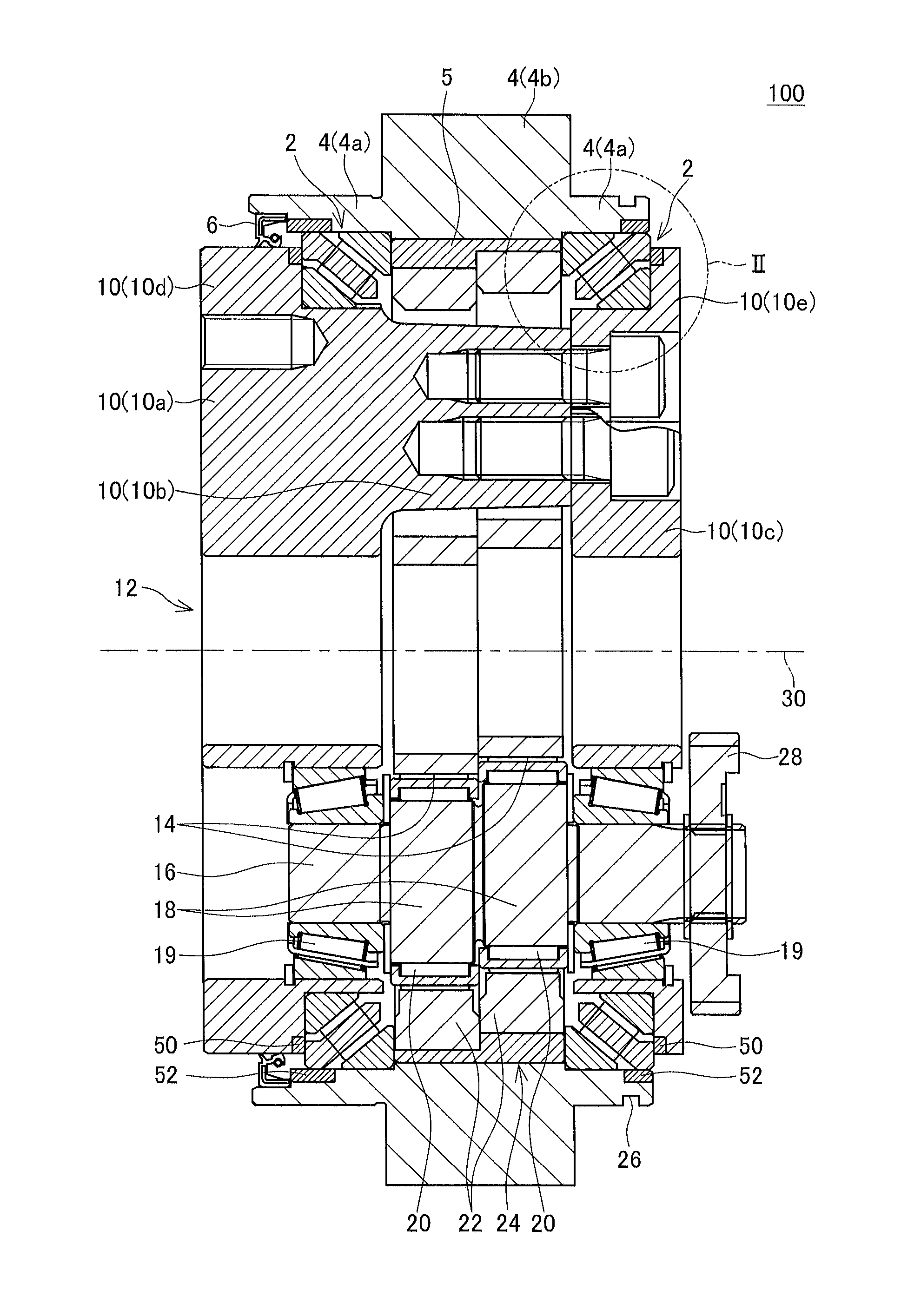
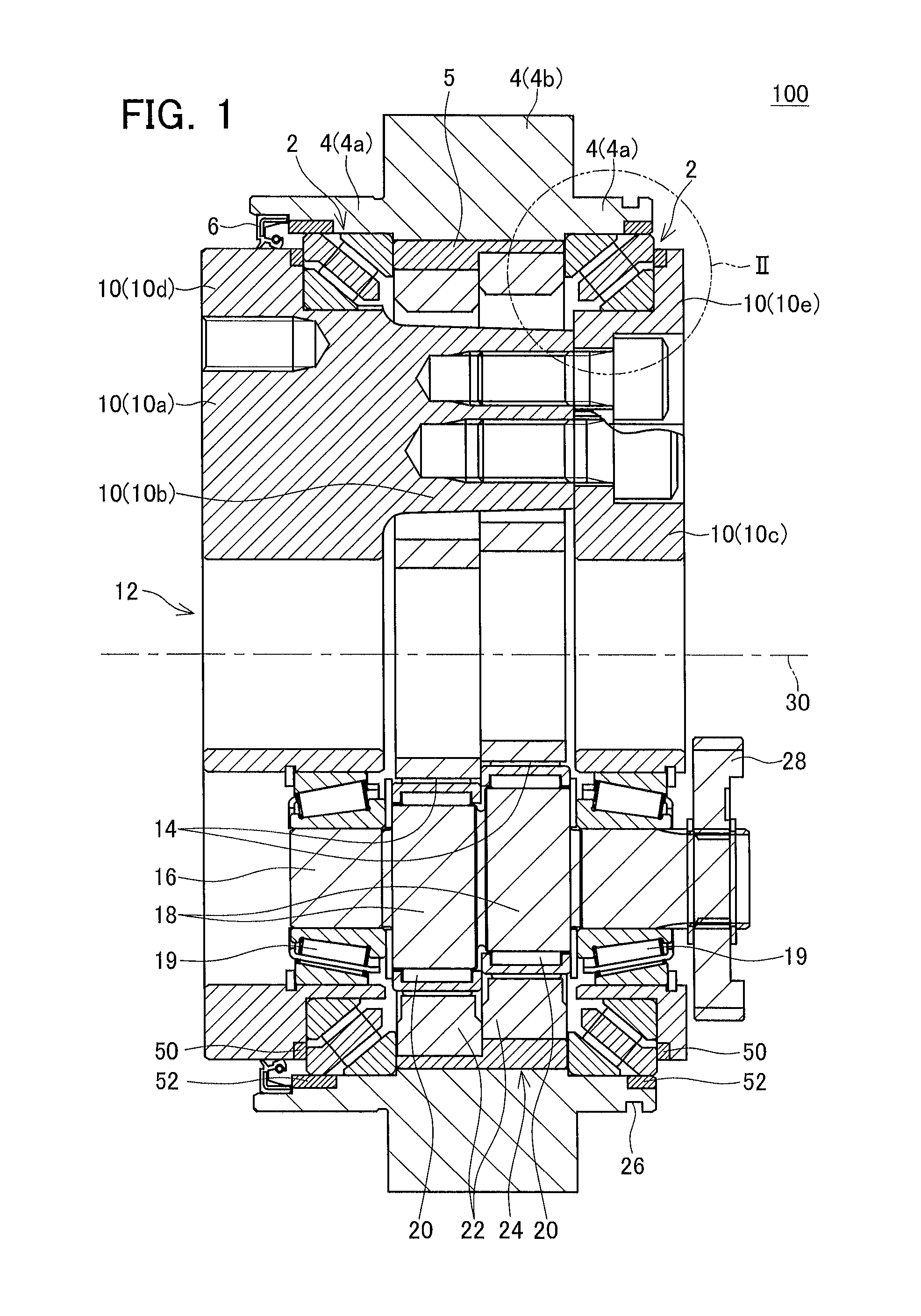
[0029]FIG. 1 shows a cross-sectional view of a gear transmission 100. The gear transmission 100 is an eccentric oscillating type reduction gear. External gears 22 rotate eccentrically while meshing with an internal gear 24. A number of teeth of each of the external gear...

second embodiment

[0057]A gear transmission of a second embodiment will be described with reference to FIGS. 7, 8. The gear transmission of the present embodiment differs from the gear transmission 100 only in a shape of a retainer. Specifically, a retainer 144 of the present embodiment differs from the retainer 44 in a positional relationship of outer circumferential grooves formed in the case contact surface, and end surface grooves formed in the carrier contact surface. Common features of the retainer 144 and the retainer 44 will be denoted by the same reference numbers or by reference numbers having the same lower two digits, and a description thereof may be thereby omitted.

[0058]Outer circumferential grooves 44f and end surface grooves 44g are formed at same positions in a circumferential direction of the retainer 144, Consequently, the outer circumferential grooves 44f and the end surface grooves 44g are contiguous. Lubricant present at the exterior of the cylindrical roller bearings 2 is intro...

third embodiment

[0059]A gear transmission of a third embodiment will be described with reference to FIGS. 9, 10. The gear transmission of the present embodiment differs from the gear transmission 100 only in a shape of a retainer. Specifically, a retainer 244 of the present embodiment differs from the retainer 44 in a shape of outer circumferential grooves formed in the case contact surface, and a shape of end surface grooves formed in the carrier contact surface. Common features of the retainer 244 and the retainer 44 will be denoted by the same reference numbers or by reference numbers having the same lower two digits, and a description thereof may be thereby omitted.

[0060]As shown in FIG. 9, a plurality of end surface grooves 244g is formed in a carrier contact surface 244e. When the end surface grooves 244g are viewed along the bearing center axis 30 direction, a direction along which the end surface grooves 244g extend is inclined with respect to a straight line joining an outer peripheral sur...


PUM


Abstract

A carrier is supported by a case via a bearing. The bearing comprises an inner race, an outer race, rollers, and a retainer. The inner race has a tapered outer peripheral surface, and is fixed to a carrier. The outer race has a tapered inner peripheral surface facing the outer peripheral surface of the inner race, and is fixed to the case. The rollers is disposed between the inner race and the outer race. An end part of the retainer having a larger diameter makes contact with the case via a first member. The larger diameter end part of the retainer makes contact with the case via a second member. By the retainer making contact with the case and the carrier via the first member and the second member, the retainer can reduce friction compared to when making direct contact with the case and the carrier.

Description

TECHNICAL FIELD[0001]This application claims priority to Japanese Patent Application No. 2013-62082, filed on Mar. 25, 2013, the contents of which are hereby incorporated by reference into the present application. The present specification discloses a technique relating to a gear transmission. In particular, the present specification discloses a technique relating to a gear transmission provided with a cylindrical roller bearing between a carrier and a case.BACKGROUND ART[0002]A gear transmission is known in which a plurality of gears is housed in a case, and a carrier is supported by the case via a bearing. A gear transmission in which a cylindrical roller bearing is disposed between a case and a carrier is disclosed in Japanese Patent Application Publication No. 2010-159774 (called Patent Document 1 below). In the cylindrical roller bearing of Patent Document 1, cylindrical rollers (rolling elements) are inclined with respect to an axis of the carrier. Since the rollers are inclin...

Claims


Application Information

Patent Timeline
Patent Type & Authority Applications(United States)
IPC IPC(8): F16C33/66F16C19/36F16C33/46F16H1/32
CPCF16C33/6681F16H1/32F16H2001/323F16C33/4605F16C19/364F16C19/361F16C33/46F16H57/021F16H57/032F16C19/548F16C2361/61
Inventor MATSUI, DAISUKEKATAOKA, YUSUKE
Owner NABLESCO CORP
Why Eureka
Try Eureka