Hydrodynamic mating ring with integrated groove inlet pressure control

Active Publication Date: 2016-02-18
EATON INTELLIGENT POWER LIMITED
View PDF7 Cites 15 Cited by
  • Summary
  • Abstract
  • Description
  • Claims
  • Application Information

AI Technical Summary

Benefits of technology

[0010]In embodiments, a method of sealing may include providing a mating ring that may include a sealing face, a plurality of hydrodynamic grooves disposed in the sealing face, a plurality of impeller portions, and/or a plurality of inlet conduits that may be configured to provide fluid communication between respective ones of

Problems solved by technology

However, when employing conventional hydrodynamic groove technology for the purpose of producing a film riding seal (e.g., non-contacting) in or under certain conditions, such as the outside environment of an aircraft at cruising altitude, the ability for a sufficient amount of fluid to enter the hydrodyna

Method used


Image

  • Hydrodynamic mating ring with integrated groove inlet pressure control
  • Hydrodynamic mating ring with integrated groove inlet pressure control
  • Hydrodynamic mating ring with integrated groove inlet pressure control

Examples


Example

[0021]Reference will now be made in detail to embodiments of the present disclosure, examples of which are described herein and illustrated in the accompanying drawings. While the disclosed concepts will be described in conjunction with embodiments, it will be understood that they are not intended to limit the disclosure to these embodiments. On the contrary, the disclosure is intended to cover alternatives, modifications and equivalents, which may be included within the spirit and scope as defined by the appended claims.

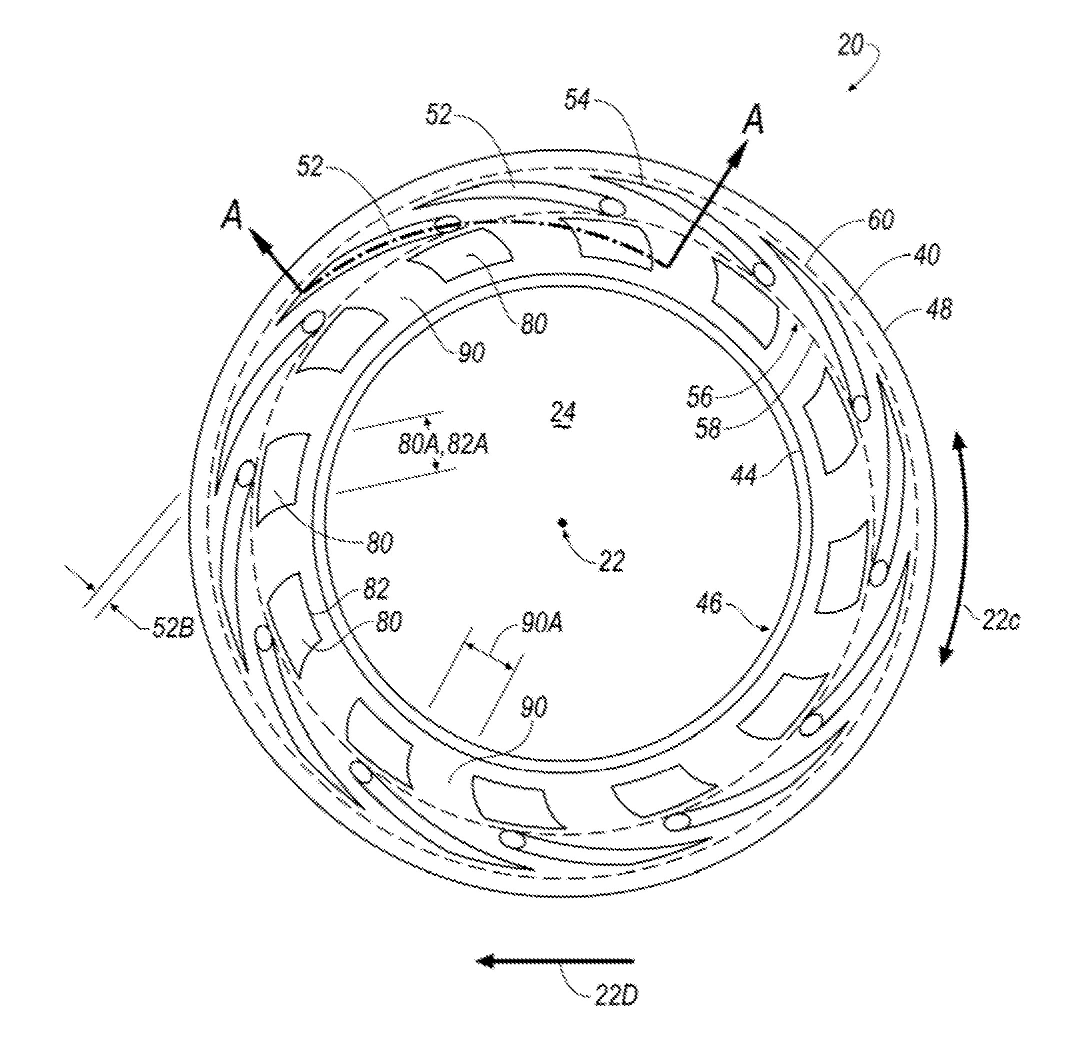
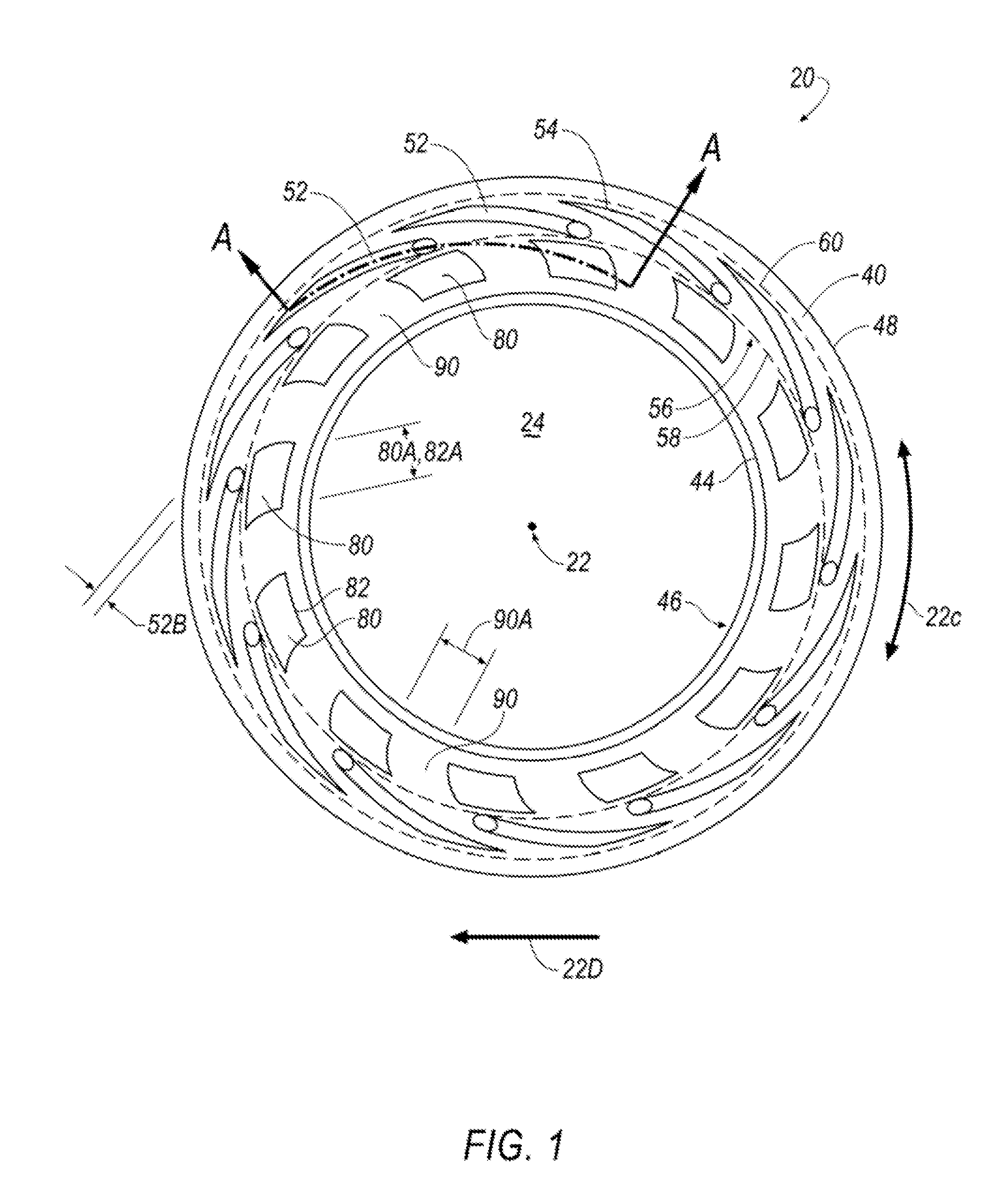
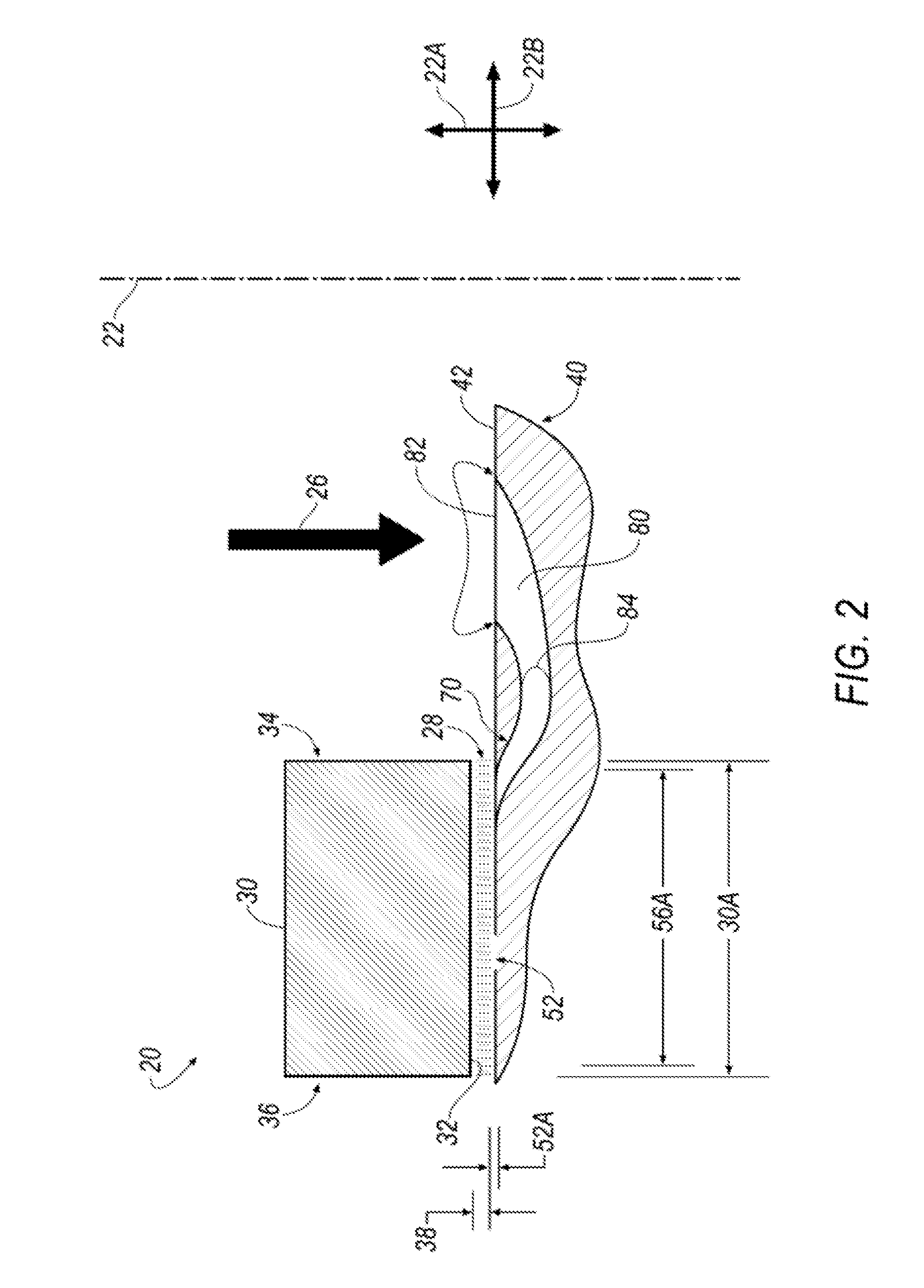
[0022]Referring to FIGS. 1 and 2, a seal assembly 20 may include a first ring 30 and a second ring 40. The first ring 30, which may also be referred to as a seal ring 30, may be stationary in terms of rotation, but for applications may be permitted to move in the axial direction 22A—e.g., along a central axis 22. An axial / sealing face 32 of the seal ring 30 may be disposed adjacent the axial / sealing thee 42 of a second ring 40. In embodiments, an axial face 32 may b...


PUM


Abstract

A hydrodynamic mating ring of the present disclosure may include a sealing face, a hydrodynamic groove disposed in the sealing face, an impeller portion, and an inlet conduit configured to provide fluid communication between the hydrodynamic groove and the impeller portion. A method of sealing may include providing a mating ring having a sealing face, a plurality of hydrodynamic grooves disposed in the sealing face, a plurality of impeller portions, and a plurality of inlet conduits configured to provide fluid communication between respective ones of the plurality of hydrodynamic grooves and the plurality of impeller portions. The method may include rotating the mating ring, and increasing at least one of a pressure, a volume, and a flow rate of fluid to the hydrodynamic grooves via the plurality of impeller portions drawing said fluid into the plurality of inlet conduits.

Description

CROSS-REFERENCE TO RELATED APPLICATIONS[0001]This application claims the benefit of U.S. Provisional Application Ser. No. 62 / 037,720, filed Aug. 15, 2014 the disclosure of which is incorporated herein by reference in its entirety.BACKGROUND[0002]1. Technical Field[0003]The present disclosure relates generally to hydrodynamic face seals.[0004]2. Description of the Related Art[0005]Spiral groove lift-off seals (also known as hydrodynamic seals or hydrodynamic face seals) have been used successfully for many years in the industrial gas compressor industry.[0006]Generally, the seal assembly involves a system fluid pressure (e.g., gas density). The high fluid pressure may be located on either an inside diameter of a seal assembly or the outside diameter of a seal assembly. The seal assemblies may comprise two rings where a face of each ring is adjacent to one another. A first ring may be a stationary member, also known as a seal ring, and may be movable only in an axial direction. A seco...

Claims


Application Information

Patent Timeline
IPC IPC(8): F16J15/34
CPCF16J15/342F16J15/3412F16J15/3404F16J15/3408
Inventor KIERNAN, GREGORY, THOMAS
Owner EATON INTELLIGENT POWER LIMITED
Why Eureka
Try Eureka