Drop-in Adjustable Trigger Assembly with Camming Safety Linkage

a safety linkage and drop-in technology, applied in the field of trigger mechanisms, can solve the problems of affecting the ability of the shooter to precisely control the trigger actuation, the shooter's ergonomics problems are exacerbated by liability lawsuits, and it is nearly impossible for the shooter or user to tune or adjust, and achieve the effect of simplifying the adjustmen

Active Publication Date: 2016-02-18
SUPERIOR SHOOTING SYSTEMS INC
View PDF0 Cites 22 Cited by
  • Summary
  • Abstract
  • Description
  • Claims
  • Application Information

AI Technical Summary

Benefits of technology

[0024]When the shooter moves the pivoting safety lever from the forward “safety off” position to the rearward “safety on” position, the sear safety linkage screw drives the lower end of the sear safety linkage rearward in the housing slots and the sear safety linkage's upper end pivots forwardly and up, pressing against and engaging the bolt sear'...

Problems solved by technology

However, safety mechanisms may interfere with trigger feel, trigger pull or other factors which directly and adversely affect the shooter's ability to precisely control trigger actuation.
Often, a marksman or precision shooter will struggle to adjust the performance on a trigger to maxim...

Method used


Image

  • Drop-in Adjustable Trigger Assembly with Camming Safety Linkage
  • Drop-in Adjustable Trigger Assembly with Camming Safety Linkage
  • Drop-in Adjustable Trigger Assembly with Camming Safety Linkage

Examples


first embodiment

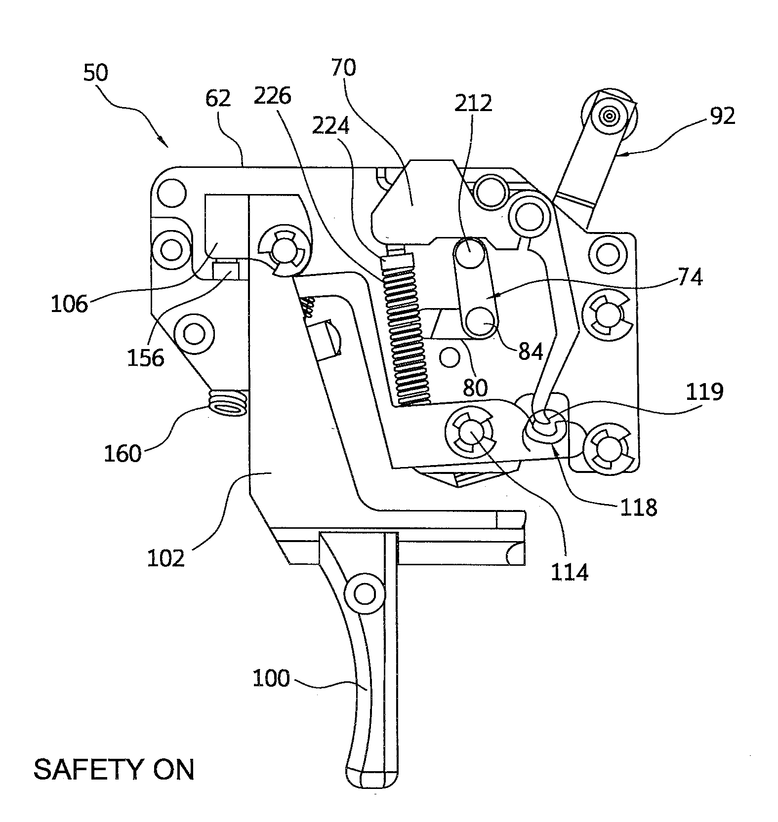
[0069]Also mounted within the sidewalls 62 and 64 are a pivotally mounted bolt sear 262 and a pivotally mounted trigger sear 264, slightly different in shape, but similar in function to the bolt sear 70 and the trigger sear 110 of the Reset pin 224 and reset spring 226 are mounted between bolt sear 262 and trigger sear 264 to reset the trigger sear, as previously described. As in the previously-described embodiment, the lower end 266 of bolt sear 262 incorporates a downwardly facing latching edge 268 which engages a corresponding upwardly facing edge 270 on trigger sear 264. The trigger mechanism 250 also incorporates a side safety bolt release lever 280 pivotally mounted on the housing's left side-plate 64.

[0070]A pivoting safety link or sear safety linkage 74 is mounted between plates 62 and 64 and has an upper camming surface 76 which engages a lower surface 272 of bolt sear 262. The housing has opposed horizontal sear safety linkage slots 80 and 82 in plates 62 and 64, respecti...

second embodiment

[0073]FIGS. 25 and 26 illustrate the “safety on” position of the safety mechanism 90, for the invention, with FIG. 25 illustrating the exterior of the right-hand side of the trigger assembly 250 and FIG. 26 illustrating the trigger assembly from the left-hand side with the housing plate 64 removed to make the interior of the assembly visible. Similarly, the “safety off” position of the safety mechanism 90 is illustrated in FIGS. 27 and 28, which show the exterior and interior views, respectively of the assembly 250.

[0074]As with the first embodiment, trigger assembly 250 incorporates user adjustable controls for a first stage weight of pull, first stage travel or movement range, second stage break weight and second stage engagement length, each of which can be optimized separately for accurate shooting. As illustrated in FIGS. 20-28, trigger mechanism 250 uses two springs, where first stage weight is adjusted by compressing spring 154 with adjustment screw 160, which preferably has ...


PUM


Abstract

A drop-in adjustable trigger assembly has a camming safety linkage to selectively move and engage a bolt sear to positively prevent movement of the bolt sear. The drop-in trigger assembly housing carries a pivoting bolt sear engagement member which is connected to a sear safety linkage. The housing has a sear safety linkage slot defined therein which guides the pivoting sear safety linkage in response to actuation of an upwardly projecting thumb safety lever's actuation. A trigger bracket preferably carries a removable, reversible trigger shoe and is configured to pivot within the housing about a pivot point within the housing, and the trigger bracket carries an adjustable rocker having (preferably) a first stage movement adjustment and a second stage length adjustment. The pivoting safety mechanism's safety linkage pivots rearwardly to push upon or cam the bolt sear upwardly, thus disengaging the bolt sear from the trigger sear.

Description

[0001]The present application claims the benefit of prior Provisional Application No. 61 / 867,049, filed Aug. 17, 2013, the disclosure of which is hereby incorporated herein in its entirety by reference.BACKGROUND OF THE INVENTION[0002]1. Field of the Invention[0003]The present invention relates to firearms and more particularly to trigger mechanisms for use in rifles and other manually actuable instruments.[0004]2. Discussion of the Prior Art[0005]Rifle marksmanship has been continuously developing over the last few hundred years, and now refinements in materials and manufacturing processes have made increasingly accurate aimed fire possible. These refinements have made previously ignored ergonomic or human factors more significant as sources of error.[0006]The term “rifle” as used here, means a projectile controlling instrument or weapon configured to aim and propel or shoot a projectile, and triggers or firearm actuator systems are discussed principally with reference to their use...

Claims


Application Information

Patent Timeline
IPC IPC(8): F41A19/06F41A17/46
CPCF41A17/46F41A19/06F41A19/12F41A17/56F41A19/15F41A19/16
Inventor TUBB, GEORGE, WYATT
Owner SUPERIOR SHOOTING SYSTEMS INC
Why Eureka
Try Eureka