Wing surface finishing method and wing component

a technology of wing surface and finishing end mill, which is applied in the direction of metal-working equipment, workpieces, milling equipment, etc., can solve the problems of difficult to maintain and achieve the effect of improving the productivity of finishing the wing surface, suppressing large frictional heat, and maintaining the durability of the finishing end mill

Active Publication Date: 2016-02-25
IHI CORP
View PDF10 Cites 2 Cited by
  • Summary
  • Abstract
  • Description
  • Claims
  • Application Information

AI Technical Summary

Benefits of technology

[0013]According to the present disclosure, even if a relative feed-movement speed of the finishing end mill becomes higher along with increase in a cutting speed of the finishing end mill, decrease in a relative feed amount per cutting edge of the finishing end mill near the leading edge or the trailing edge of the wing surface corresponding area of the workpiece can be suppressed. Therefore, large frictional heat can be suppressed from being generated between the finishing end mill and the workpiece to thereby maintain durability of the finishing end mill, while improving productivity of finishing of the wing surface of the wing member.

Problems solved by technology

That is, there is a problem that it is difficult to maintain the durability of the finishing end mill 10A (20A), while improving the productivity of finishing of the wing surface S1 (S2) of the wing member M1 (M2).

Method used


Image

  • Wing surface finishing method and wing component
  • Wing surface finishing method and wing component
  • Wing surface finishing method and wing component

Examples


first embodiment

[0026]A first embodiment of the present disclosure will be explained with reference to FIGS. 1A, 1B, 2A and 2B.

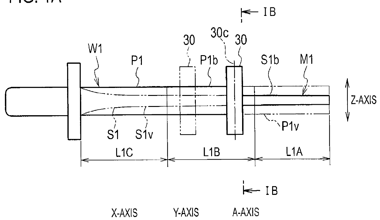
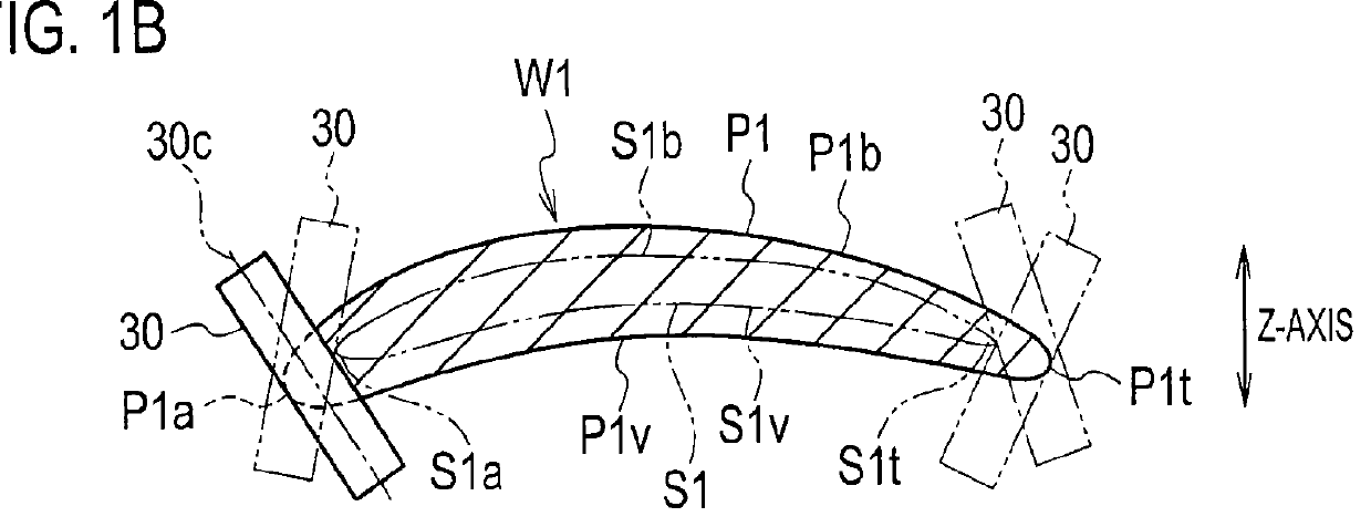
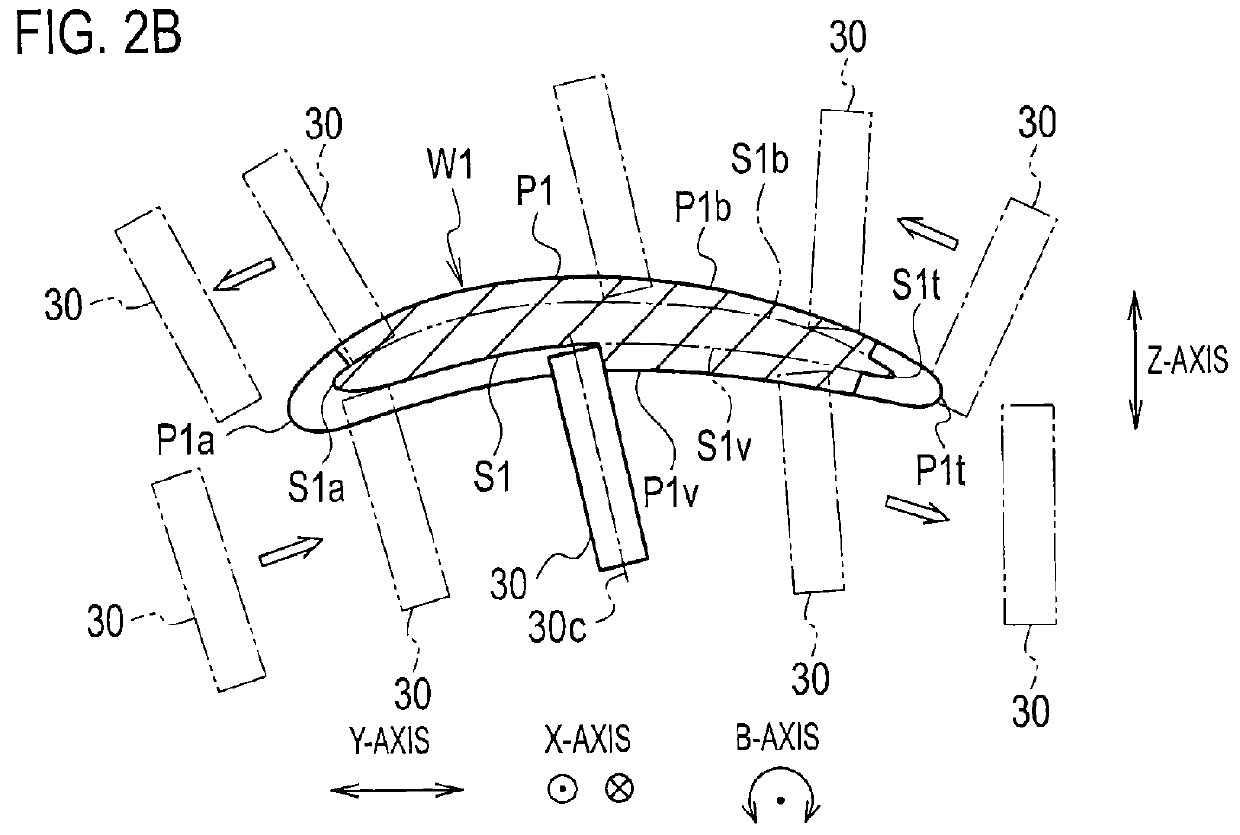
[0027]As shown in FIGS. 1A to 2B, a wing surface finishing method according to the embodiment is the method for applying finishing processing to a wing surface corresponding area P1 of a roughly-processed workpiece W1 set to a work jig (not shown) of a machining center, and finishing it into a wing surface S1 of a wing component M1 as a wing member. In addition, in the wing surface finishing method according to the embodiment, the wing surface corresponding area P1 of the workpiece W1 is divided into a plurality of (three in the first embodiment) sections L1A, L1B, and L1C from a tip to a base end, and a series of steps including a first finishing step (1-1), a second finishing step (1-2), a third finishing step (1-3), and a fourth finishing step (1-4) is sequentially executed from a tip side in the plurality of sections L1A, L1B, and L1C. Note that execution of each step i...

second embodiment

[0041]A second embodiment of the present disclosure will be explained with reference to FIGS. 3A, 3B, 4A, and 4B.

[0042]As shown in FIGS. 3A to 4B, a wing surface finishing method according to the embodiment is the method for applying finishing processing to a wing surface corresponding area P2 of a roughly-processed workpiece W2 set to a work jig (not shown) of a machining center, and finishing the wing surface corresponding area P2 of the workpiece W2 into a wing surface S2 of a wing wheel component member M2 as a wing member. In addition, in the wing surface finishing method according to the embodiment, the wing surface corresponding area P2 of the workpiece W2 is divided into a plurality of (three in the second embodiment) sections L2A, L2B, and L2C from a tip to a base end, and a series of steps including a first finishing step (2-1), a second finishing step (2-2), a third finishing step (2-3), and a fourth finishing step (2-4) is sequentially executed from a tip side in the plu...


PUM

PropertyMeasurementUnit
areaaaaaaaaaaa
speedaaaaaaaaaa
area P1aaaaaaaaaa

Abstract

A wing surface finishing method is the one in which after finishing of a leading edge and a trailing edge and finishing of a ventral portion and a back portion in a wing surface of a wing component are separated into separate steps, a finishing end mill is made to approach a ventral portion and a back portion of awing surface corresponding area of a workpiece after a speed of the finishing end mill is increased, finishing processing is applied to the ventral portion and the back portion of the wing surface corresponding area of the workpiece, respectively, and the speed of the finishing end mill is decreased after the finishing end mill is moved away from the wing surface corresponding area of the workpiece.

Description

CROSS REFERENCE TO RELATED APPLICATIONS[0001]This application is a continuation application of International Application No. PCT / JP2013 / 062995, filed on May 9, 2013, the entire contents of which are incorporated by reference herein.BACKGROUND[0002]1. Field[0003]The present disclosure relates to a wing surface finishing method etc. for applying finishing processing to a wing surface corresponding area of a roughly-processed workpiece, and finishing it into a wing surface of a wing member.[0004]2. Description of the Related Art[0005]Generally, wing members used for a compressor or a turbine of a gas turbine can be classified into a single wing component, and a wing wheel component member of an integrated wing wheel (a blisk). Additionally, the wing component and a wing surface of the wing wheel component member as the wing members are usually finished as follows by applying finishing processing to a wing surface corresponding area of a roughly-processed workpiece.[0006]As shown in FIG...

Claims


Application Information

Patent Timeline
Patent Type & Authority Applications(United States)
IPC IPC(8): B23C3/18
CPCB23C2220/28B23C3/18B23C5/1081B23C2215/44B23C2220/04B23C2220/32Y10T409/303808Y10T409/30756
Inventor OCHIAI, HIROYUKIKUWAHARA, KENGOTAKEKAWA, TOSHIHISA
Owner IHI CORP
Why Eureka
Try Eureka