Method for removing brittle-hard material by means of laser radiation

a laser radiation and brittle material technology, applied in glass making apparatus, manufacturing tools, welding/soldering/cutting articles, etc., can solve the problems of interference diffraction patterns, laser radiation focusing, and the difficulty of conventional machining (cutting, drilling) for thin glass panes

Inactive Publication Date: 2016-02-25
FRAUNHOFER GESELLSCHAFT ZUR FOERDERUNG DER ANGEWANDTEN FORSCHUNG EV +1
View PDF21 Cites 4 Cited by
  • Summary
  • Abstract
  • Description
  • Claims
  • Application Information

AI Technical Summary

Benefits of technology

[0010]The principal objective addressed by the invention is that of providing a method that avoids or at least prevents to a large degree the damages described above, which, in particular arise from the entry edge or the cause of which can be traced to the laser radiation that impacts the entry edge.

Problems solved by technology

Conventional machining (cutting, drilling) is much more difficult for thin glass panes than for large material thicknesses.
This produces interference diffraction patterns through radiation portions of the laser radiation.
As soon as these radiation portions again incise on the surfaces of the removal depression, the respective surface is roughened; the refractive effect of the roughness results in focusing of the laser radiation and cracks can be caused in the adjacent material.
In addition, the entry edge in the region of the forming removal depression has a very large impact on the formation of the removal depression and the forming of cracks.
Damage in the shape of cracks arises from this entry edge, and the laser radiation that incises on the entry edge appears to be the cause of it.

Method used


Image

  • Method for removing brittle-hard material by means of laser radiation
  • Method for removing brittle-hard material by means of laser radiation
  • Method for removing brittle-hard material by means of laser radiation

Examples


Embodiment Construction

[0047]The preferred embodiments of the present invention will now be described with reference to FIGS. 1-11 of the drawings. Identical elements in the various figures are designated with the same reference numerals.

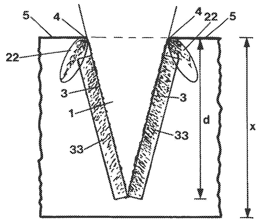
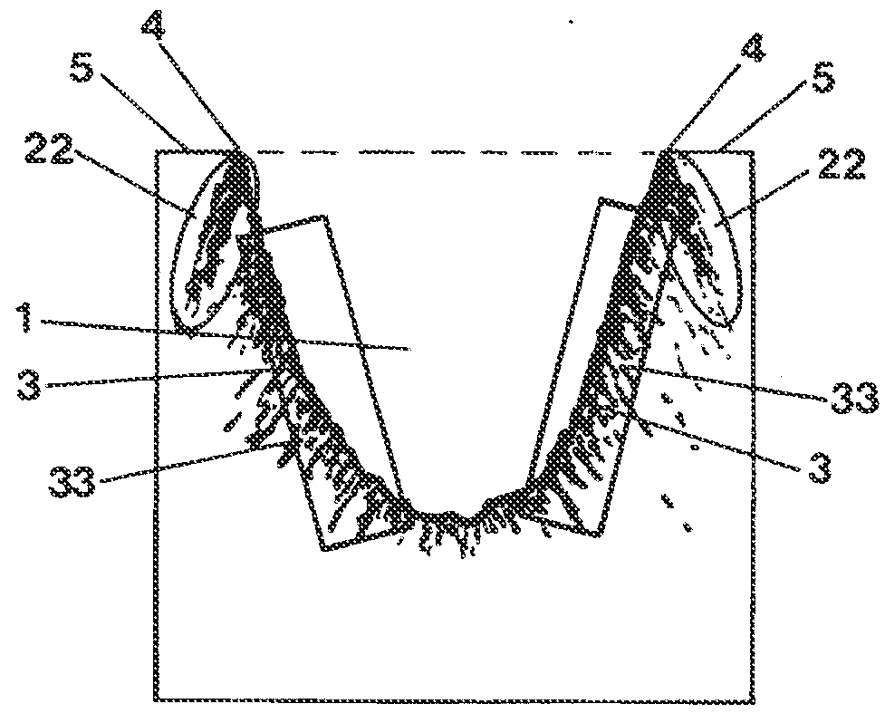
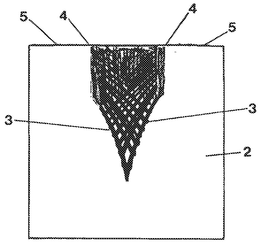
[0048]The representation of FIG. 1 shows schematically a V-shaped removal depression 1 that is formed in a thin glass material 2 with a thickness x. This removal depression 1 has removal flanks 3 originating from an entry edge 4 on the surface 5 of the material.

[0049]The following definitions apply to the various terms that are used here:

[0050]Threshold value ρablation is the threshold value of the electron density at which an ablation / a removal starts,

[0051]Threshold value ρdamage is the threshold value of the electron density at which damages / cracks start,

[0052]Pulse parameter is a set of parameters for characterizing the spatial, time and spectral properties of the incident laser radiation. The pulse parameter includes at least the values for[0053]Pulse duration,[0054]...


PUM

PropertyMeasurementUnit
wavelengthaaaaaaaaaa
sizeaaaaaaaaaa
electron densityaaaaaaaaaa

Abstract

Laser radiation is used for removing brittle-hard material from a substrate without damaging the material. A removal depression having a flank angle w of the flanks of the removal depression forms in the material as a result of the removal. The removal depression forms with an entry edge, which is defined as a spatially expanded region of the surface of the material, where an unchanged and thus unremoved portion of the surface of the material transitions into the removal depression. Spatial portions of the laser radiation are refracted and focused into the volume of the unremoved material at this entry edge. The distribution of the laser radiation is set such that the entry edge assumes a small spatial expansion, such that the portion of the power of the laser radiation, which is captured by the focusing effect of the entry edge, is not sufficient to generate a threshold value ρdamage for the electron density in the volume of the material, thus avoiding damage to the material.

Description

BACKGROUND OF THE INVENTION[0001]The invention relates to a method for removing, for example cutting, scoring, drilling, brittle-hard material by means of laser radiation, wherein a removal depression having a flank angle w of the flanks of the removal depression forms in the material as a result of the removal, wherein the flank angle w is defined as the angle between the surface normal on the flank of the removal depression and the surface normal on the unremoved surface of the material, and forms with an entry edge, which is defined as a spatially expanded region of the surface of the material, where an unchanged and thus unremoved portion of the surface of the material transitions into the removal depression, and at which spatial portions of the laser radiation are refracted and focused into the volume of the unremoved material.[0002]Such methods are used in display technology, among other fields, where thin glass substrates, a brittle-hard material, must be machined. In particu...

Claims


Application Information

Patent Timeline
Patent Type & Authority Applications(United States)
IPC IPC(8): B23K26/00B23K26/361C03B33/02
CPCB23K26/0006C03B33/0222B23K26/361B23K26/0604B23K26/0613B23K26/36B23K26/382B23K26/40B23K2103/50
Inventor SCHULZ, WOLFGANGEPPELT, URS
Owner FRAUNHOFER GESELLSCHAFT ZUR FOERDERUNG DER ANGEWANDTEN FORSCHUNG EV
Why Eureka
Try Eureka