Lidar system

a technology of sliding system and laser power, applied in the field of sliding system, can solve the problems of limited sliding system, inability to detect photons and evaluate reflected signals, and the possibility of not being able to arbitrarily increase laser power, etc., to achieve the effect of avoiding or avoiding

Inactive Publication Date: 2019-02-07
ROBERT BOSCH GMBH
View PDF0 Cites 0 Cited by
  • Summary
  • Abstract
  • Description
  • Claims
  • Application Information

AI Technical Summary

Benefits of technology

[0008]According to the present invention, a LIDAR system is made available, which avoids or at least considerably reduces the problems occurring in the related art regarding the eye safety of coherent laser radiation at high powers. The LIDAR system according to the present invention is preferably a non-coherently detecting LIDAR. In the case of such a LIDAR, the phase (or the phase relation within the radiation field) of the laser radiation utilized for scanning the surroundings will not be taken into consideration.

Problems solved by technology

The range of a LIDAR system is limited, inter alia, by the fact that fewer and fewer photons return to the detector as the distance to a reflecting surface increases and, at some point, the detection of the photons and an evaluation of the reflected signal becomes no longer possible.
This is a critical limitation, in particular, at wavelengths in the visible and near infrared spectral ranges (wavelengths below 1.4 μm), because such light penetrates the cornea and the lens of the eye particularly well and, therefore, may be focused onto the sensitive retina.
Due to the requirements on eye safety, the laser power may therefore not be arbitrarily increased.
In the case of coherent laser radiation having corresponding wavelengths, the risk to the eye lies, in particular, in the fact that the coherent light may be focused very well by the lens of the eye onto individual points of the sensitive retina.
As a result, very high power densities may occur at this point, which may irreversibly destroy the sensitive tissue of the retina.
Although the use of incoherent laser radiation would increase the size of the effective focal point, such radiation, however, has a considerably higher divergence and, therefore, is not suitable for a high-resolution scanning of the surroundings.
Nevertheless, a limitation of the superposition to, at most, three propagation modes of a mode family is mostly completely sufficient for an approximation of a real laser radiation.
However, these methods are mostly impracticable, inefficient, or very expensive.

Method used


Image

  • Lidar system
  • Lidar system

Examples


Embodiment Construction

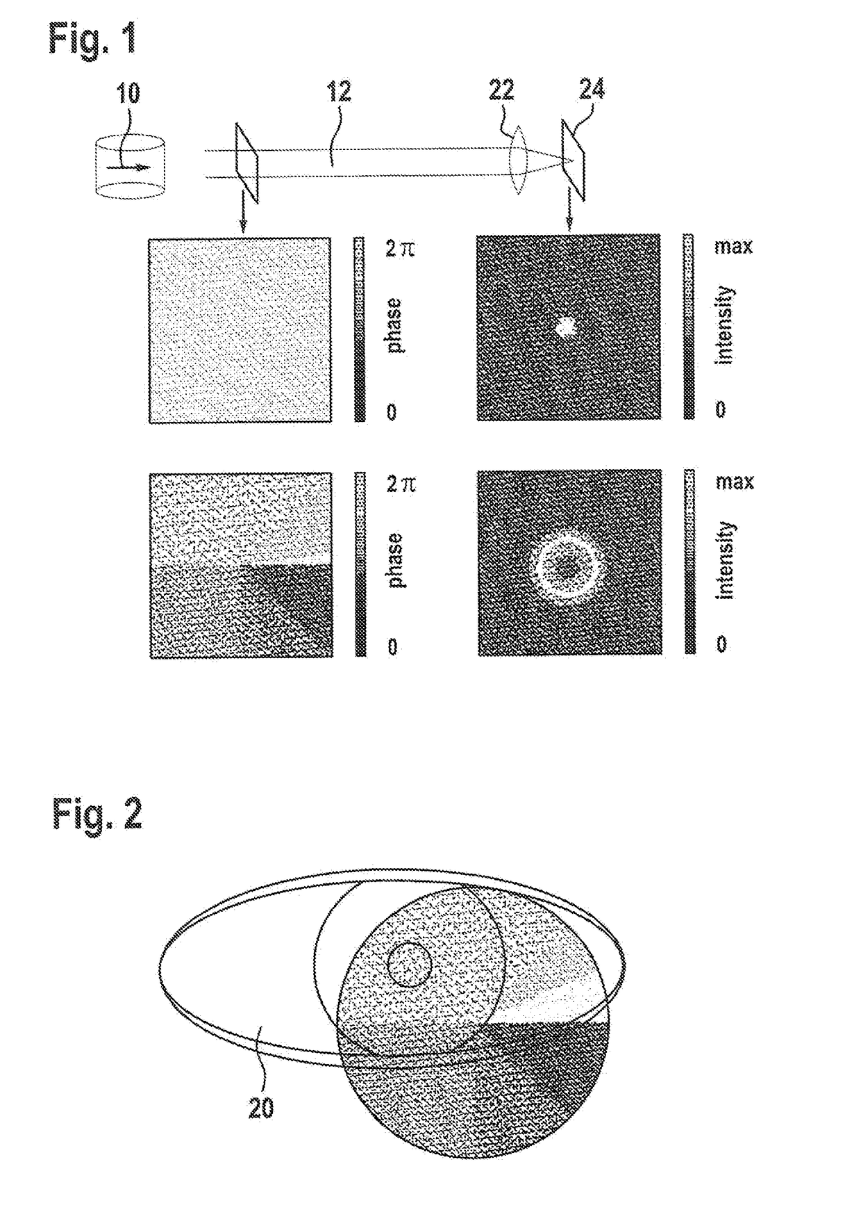
[0035]FIG. 1 shows phase fronts of collimated beams and intensity distributions after focusing, using the example of a Gaussian beam (top) and a higher-order Laguerre-Gaussian beam according to the present invention (bottom). Moreover, a LIDAR system including a laser radiation source 10 for generating coherent laser radiation 12 is schematically represented, generated laser radiation 12 being focused onto an image plane by a lens 22 in the further progression of the beam. In particular, lens 22 may be lens  of an eye 20 and image plane 24 may be a corresponding retina 24.

[0036]The particular phase fronts (phase distribution) before the focusing are represented for the cutting plane indicated close to the LIDAR system and the corresponding intensity distributions in the image plane after the focusing are represented for the cutting plane indicated far from the LIDAR system. The upper row shows typical distributions for a Gaussian beam of a conventional LIDAR system. The lower row sh...


PUM


Abstract

A LIDAR system which includes a laser radiation source for generating coherent laser radiation, the LIDAR system being designed for emitting the laser radiation emitted by the LIDAR system essentially in propagation modes which correspond to analytical solutions of the paraxial Helmholtz equation including two ordinal numbers, at least one of the two ordinal numbers being greater than 0.

Description

CROSS REFERENCE[0001]The present application claims the benefit under 35 U.S.C. § 119 of German Patent No. DE 102017213706.1 filed on Aug. 7, 2018, which is expressly incorporated herein by reference in its entirety.FIELD[0002]The present invention relates to a LIDAR system, preferably an eye-safe LIDAR system.BACKGROUND INFORMATION[0003]LIDAR (Light Detection and Ranging) is becoming increasingly significant in the surroundings detection of motor vehicles or robots. Even though various technical specific embodiments exist, the presence, distance, and, if necessary, speed of other objects is generally detected by emitting light and subsequently detecting the radiation reflected by illuminated surfaces. In particular, a laser beam may be utilized for scanning the surroundings. A typical method is based on the approach that individual laser pulses are emitted in rapid succession by an appropriate LIDAR system in different spatial directions in order to scan the surroundings and the di...

Claims


Application Information

Patent Timeline
Patent Type & Authority Applications(United States)
IPC IPC(8): G01S17/89G01S7/481
CPCG01S17/89G01S7/4817G01S7/481G01S17/02G01S7/4814
Inventor RAMSTEINER, INGOFREDERIKSEN, ANNETTEGRAF, TOBIAS
Owner ROBERT BOSCH GMBH
Why Eureka
Try Eureka