Automated Paint Application System and Related Method

a paint application system and paint technology, applied in the field of paint applicators, can solve problems such as injuries or even death

Inactive Publication Date: 2016-02-25
GRIMES JOHN
View PDF10 Cites 16 Cited by
  • Summary
  • Abstract
  • Description
  • Claims
  • Application Information

AI Technical Summary

Benefits of technology

[0076]a fastening arrangement for removably securing said at lea...

Problems solved by technology

While this methodology has worked in the past, it has often lead to injuries or even death due to th...

Method used


Image

  • Automated Paint Application System and Related Method
  • Automated Paint Application System and Related Method
  • Automated Paint Application System and Related Method

Examples


Embodiment Construction

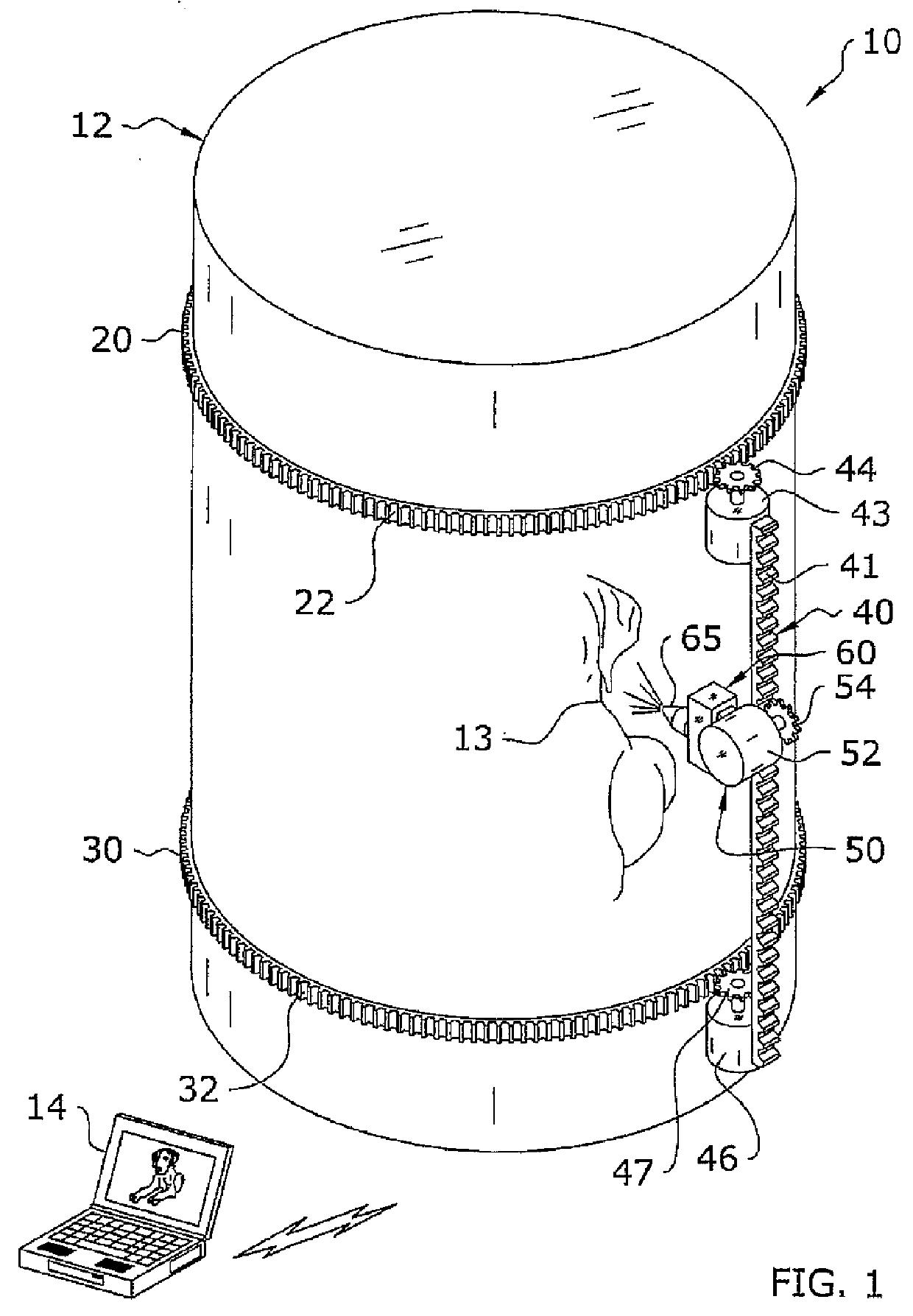
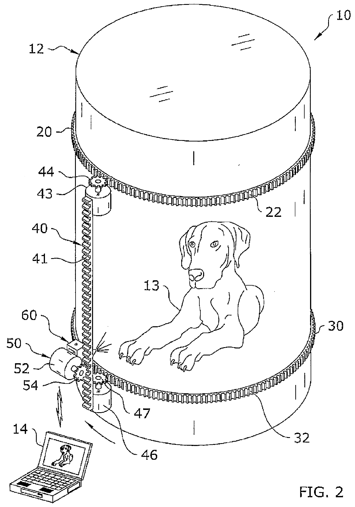
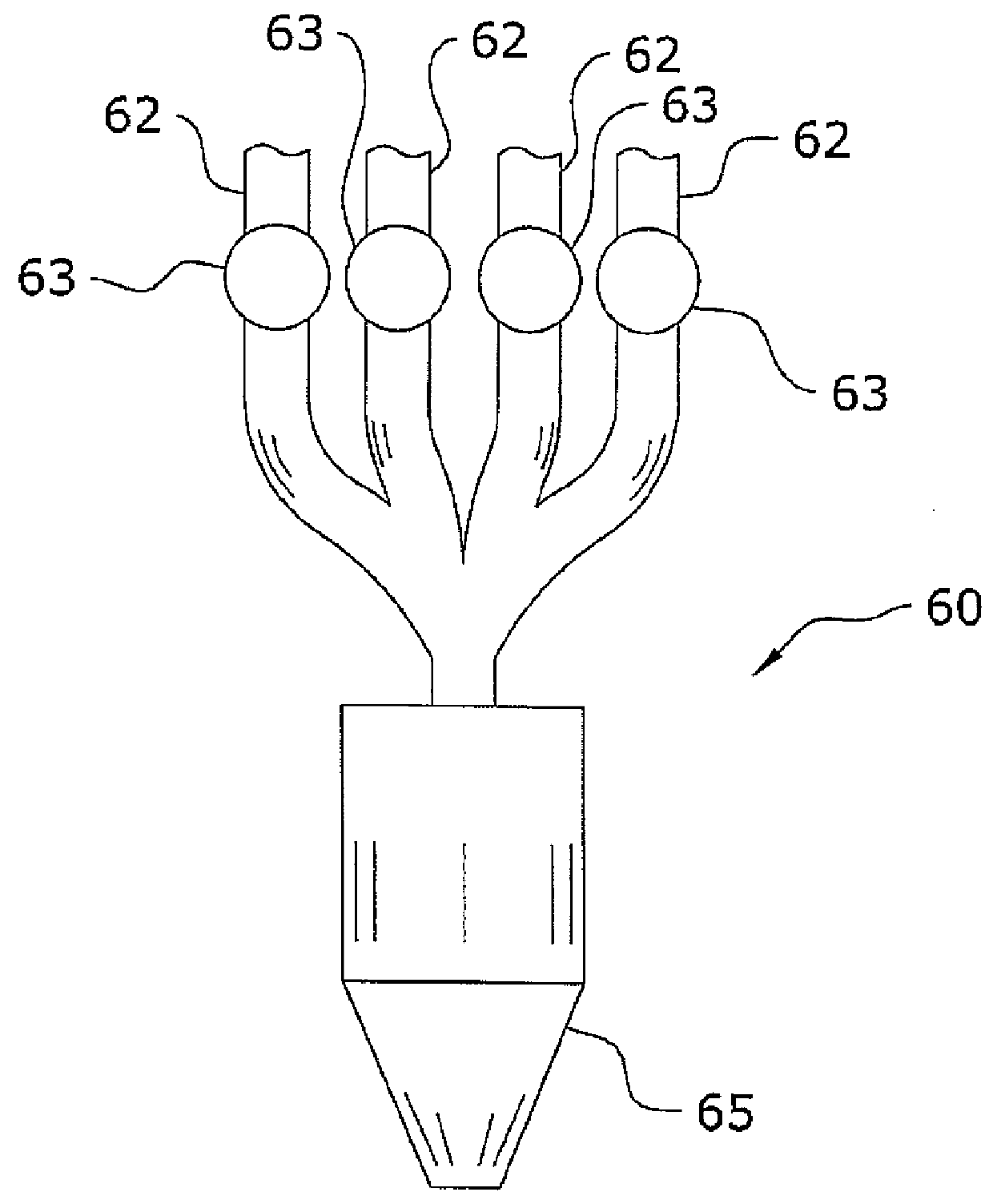
[0101]In FIGS. 1-5, there is illustrated a first arrangement of an automated paint application system 10, which comprises an first track 20 and a second track 30 which are secured to a structure in parallel relationship with each other. An applicator mount 40 is vertically secured between the first and second tracks 20, 30. Sprockets 44, 47 are utilized on the tracks 20, 30 to allow the applicator mount 40 to horizontally traverse the tracks 20, 30. A paint applicator 60 movably secured to the applicator mount 40 through use of an applicator sprocket 54 such that the paint applicator 60 may vertically traverse the applicator mount 40. A controller 14 may be provided to direct the automated paint application system to position itself and dispense paint in a manner which automatically paints an image 13 on the structure 12. The controller may be linked in a wired manner or wirelessly.

[0102]As shown in FIGS. 1 and 2, the automated paint application system utilizes a pair of tracks 20, ...


PUM

PropertyMeasurementUnit
Pressureaaaaaaaaaa
Flow rateaaaaaaaaaa
Densityaaaaaaaaaa

Abstract

An automated paint application system for automatically, safely and efficiently reproducing a high resolution image on an area of a surface located in an uncontrolled environment and a related method for reproducing a high resolution image on a surface in an uncontrolled environment are disclosed. The automated paint application system features a robotic painting machine which uses a vectorized format of the image to generate a plurality of paint paths which an applicator nozzle of the robotic painting machine follows about the surface in order to form the image. The robotic painting machine includes a plurality of paint conduits each connected by a valve to at least one applicator nozzle and usable for respectively transferring a different coloured paint in a manner such that the valves are controllable to dispense one of the different coloured paints or to form a combination colour thereof.

Description

[0001]This application is a continuation-in-part of U.S. parent application Ser. No. 13 / 776,120, filed Feb. 25, 2013.FIELD OF THE INVENTION[0002]The present invention relates generally to a paint applicator and more specifically it relates to an automated paint application system for automatically, safely and efficiently painting an image onto a structure.BACKGROUND[0003]Large structures such as water towers, grain storage buildings and the like often have large images painted on them. For example, water towers often have the name of a town or city painted thereon, sometimes with an additional image. Large buildings will often have advertisements or signs painted on their sides.[0004]When painting images on such large structures, it is often required that a painter go up on a scaffolding or other device and manually paint the image. While this methodology has worked in the past, it has often lead to injuries or even death due to the hazards related with being suspended next to a lar...

Claims


Application Information

Patent Timeline
IPC IPC(8): B41J3/407
CPCB41J3/4073B05B12/00B05B12/1409B05B12/1418B05B13/005B05B13/0405B05B13/041B05B13/0431B41M5/0082B05D1/02
Inventor GRIMES, JOHN
Owner GRIMES JOHN
Why Eureka
Try Eureka