Robot cleaner

a robot cleaner and cleaner technology, applied in the field of robot cleaners, to achieve the effect of reducing the amount of materials used and therefore the cost of manufacture, maximizing the effectiveness of each stage, and reducing the weight of the machin

Inactive Publication Date: 2016-03-03
DYSON TECH LTD
View PDF1 Cites 28 Cited by
  • Summary
  • Abstract
  • Description
  • Claims
  • Application Information

AI Technical Summary

Benefits of technology

[0009]The front portion may be downwardly sloped towards the front edge of the body, and the protrusion may have a forward-facing edge that extends vertically from the sloped front portion. Accordingly, when the sloped front of the robot cleaner gives rise to an increased risk of wedging, the vertical front edge of the protrusion will counteract the risk by abutting against any oncoming obstacles and preventing the front portion from becoming wedged under the obstacle.
[0010]The protrusion may comprise two stages, a lower stage extending to a height that is at least equal to the height of the top surface of the body, and an upper stage extending to a height that is at least equal to the height of the sensor. As a result, the lower stage of the protrusion can protect the robot cleaner against the risk of the front of the robot becoming wedged, whilst the upper stage of the protrusion can protect the sensor from damage. The two stages may be shaped and sized differently to maximise the effectiveness of each stage for the function that it is required to carry out. For example, the part of the protrusion that protects the sensor may not need to be as large as the part of the protrusion that protects against wedging, and so the upper stage can be made smaller than the lower stage. This reduces the amount of materials used and therefore cost of manufacture, and also reduces the weight of the machine. It also allows the part of the protrusion that is visible to the sensor to be made smaller such that is presents a smaller visible obstruction in the field of view of the sensor.
[0011]The forward facing edge of the upper stage may be positioned behind the forward-facing edge of the lower stage. This allows the robot to travel further under an obstacle if there is no risk of wedging before being forced to stop. This allows the robot cleaner to cover a greater area when cleaning around obstacles that could cause damage to the sensor.
[0012]The sensor may be one of an infra-red sensor assembly, a laser distance sensor assembly and a camera assembly. The camera assembly may be a panoramic annular lens camera which comprises a dome-shaped lens protruding from the top surface of the body. By using a PAL camera a 360° omni-directional image of the area surrounding the robot can be captured, and the robot cleaner can more effectively navigate around an environment in which it is located.
[0013]The body may comprise a separating apparatus part that is removable from the remainder of the body and the protrusion may be provided on the separating apparatus part. By locating the separating apparatus part at the front of the robot cleaner, it acts as a resilient bumper for the robot cleaner when it comes into contact with obstacles. The separating apparatus part does not contain any delicate electronics, unlike the remainder of the body of the robot cleaner, and so there is a reduced risk of any collisions with obstacles causing damage to the electronics and controls. Therefore, it is also beneficial to position the protrusion on the separating apparatus part, as it will reduce the risk of any collision with the protrusion causing damage to any of the electronics or other delicate parts of the robot.
[0014]What is more, by positioning the protrusion on the top of the removable separating apparatus part, if it is damaged during use it is much easier and cheaper to replace the separating apparatus part than to try and fix or replace the remainder of the body.

Problems solved by technology

For example, some robots utilise infra-red detectors that allow the robot to navigate towards an IR beacon, and some robots use complex vision systems that utilise cameras to view, understand and navigate around a local environment surrounding the robot.

Method used


Image

  • Robot cleaner
  • Robot cleaner
  • Robot cleaner

Examples


Embodiment Construction

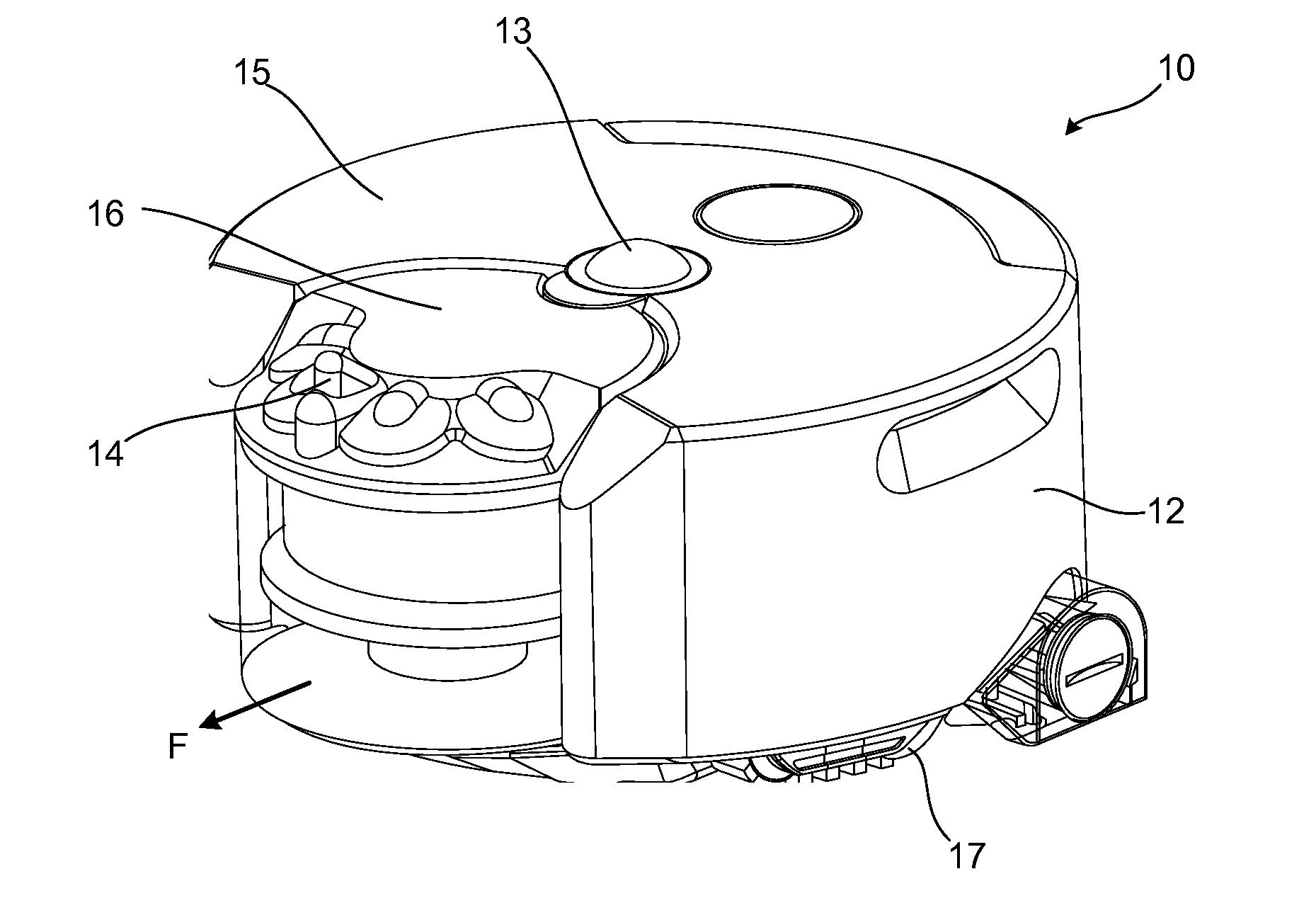
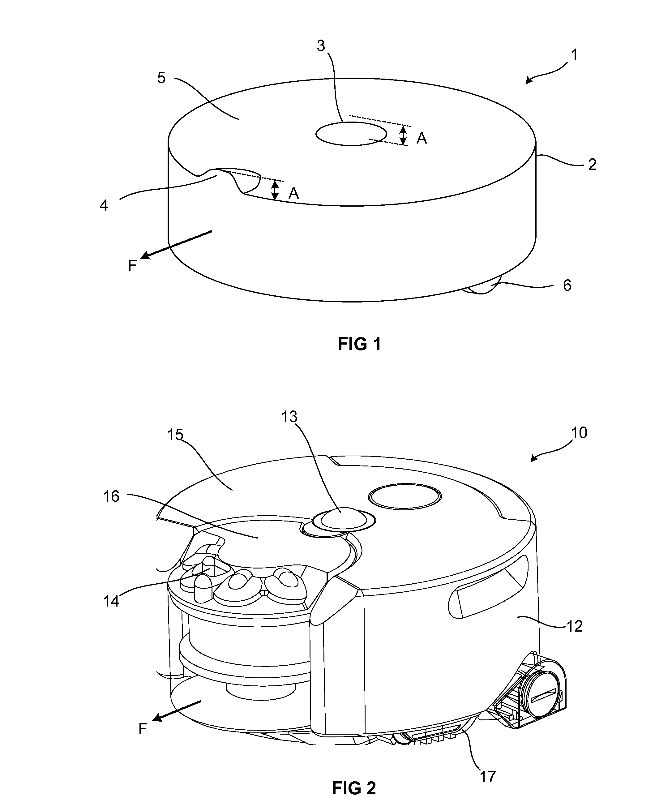
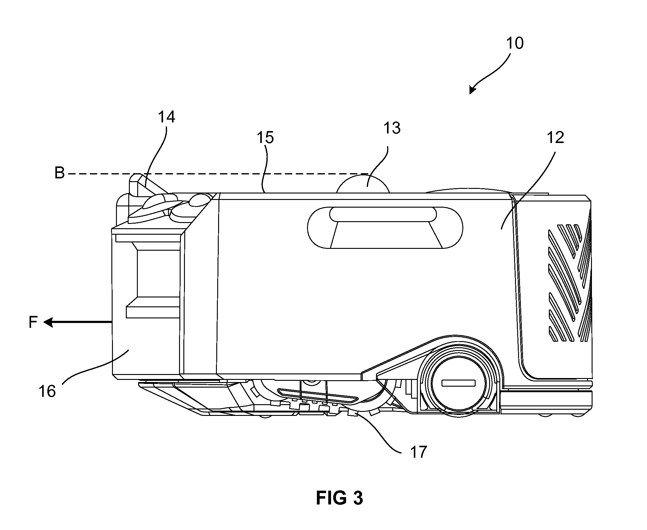
[0022]FIG. 1 shows a first embodiment of a robot cleaner 1. The robot cleaner 1 comprises a body 2. A sensor 3 is provided on the top surface 5 of the body 2. The sensor 3 protrudes above the top surface 5 of the body 2 which allows the sensor 3 to be omnidirectional and work in any direction around the robot if required. For example, the sensor 3 could be an infra-red sensor assembly that is able to detect an IR beam, a laser distance sensor assembly, or a camera assembly. The sensor 3 could be a camera assembly in the form of a panoramic annular lens (PAL) camera. By protruding from the top surface of the robot cleaner 1, a PAL camera is able to capture a 360° image around the robot cleaner 1. Drive units 6, for example wheels, are provided on the robot to allow it to drive autonomously around a local environment.

[0023]The sensor 3 protrudes above the top surface 5 of the body 2 and so is vulnerable to damage while the robot cleaner moves around a room, for example from low furnit...


PUM

PropertyMeasurementUnit
heightaaaaaaaaaa
areaaaaaaaaaaa
weightaaaaaaaaaa

Abstract

A robot cleaner comprising: a body; and a sensor protruding from a top surface of the body, wherein the body comprises a protrusion positioned forward of the sensor relative to a forward driving direction of the robot cleaner, the protrusion extending to a height that is at least equal to the height of the sensor.

Description

REFERENCE TO RELATED APPLICATIONS[0001]This application claims priority of United Kingdom Application No. 1415607.9, filed on Sep. 3, 2014, the entire contents of which are incorporated herein by reference.FIELD OF THE INVENTION[0002]The present invention relates to a robot cleaner.BACKGROUND OF THE INVENTION[0003]Mobile robots are becoming increasingly commonplace and are used in such diverse fields as space exploration, lawn mowing and floor cleaning. Recently there has been a rapid advancement in the field of robotic cleaning devices, especially robot vacuum cleaners and floor mopping robots, the primary objective of which is to navigate a user's home autonomously and unobtrusively whilst cleaning the floor.[0004]In performing this task, a robotic cleaner has to navigate the area which it is required to clean. Robots are usually provided with a number of sensors that enable them to navigate around an environment. A large variety of sensors have been employed on robots to assist w...

Claims


Application Information

Patent Timeline
Patent Type & Authority Applications(United States)
IPC IPC(8): A47L11/40G05D1/02
CPCA47L7/00A47L2201/00G05D1/0246G05D1/0242G05D2201/0203A47L2201/04A47L11/4061Y10S901/01A47L11/40G05D1/024A47L9/00A47L9/009
Inventor DYSON, JAMESALDRED, MICHAEL, DAVIDGARNER, LEANNE, JOYCE
Owner DYSON TECH LTD
Why Eureka
Try Eureka