Rotary atomizing head type coating machine

a coating machine and atomizer technology, applied in the direction of induction-charge spraying, movable spraying apparatus, electrostatic spraying apparatus, etc., can solve the problems of inability to micronize paint, deterioration of controllability of spray pattern, etc., to achieve easy processing and washing, small air consumption amount, and easy to wash

Active Publication Date: 2016-03-03
ABB (SCHWEIZ) AG
View PDF5 Cites 10 Cited by
  • Summary
  • Abstract
  • Description
  • Claims
  • Application Information

AI Technical Summary

Benefits of technology

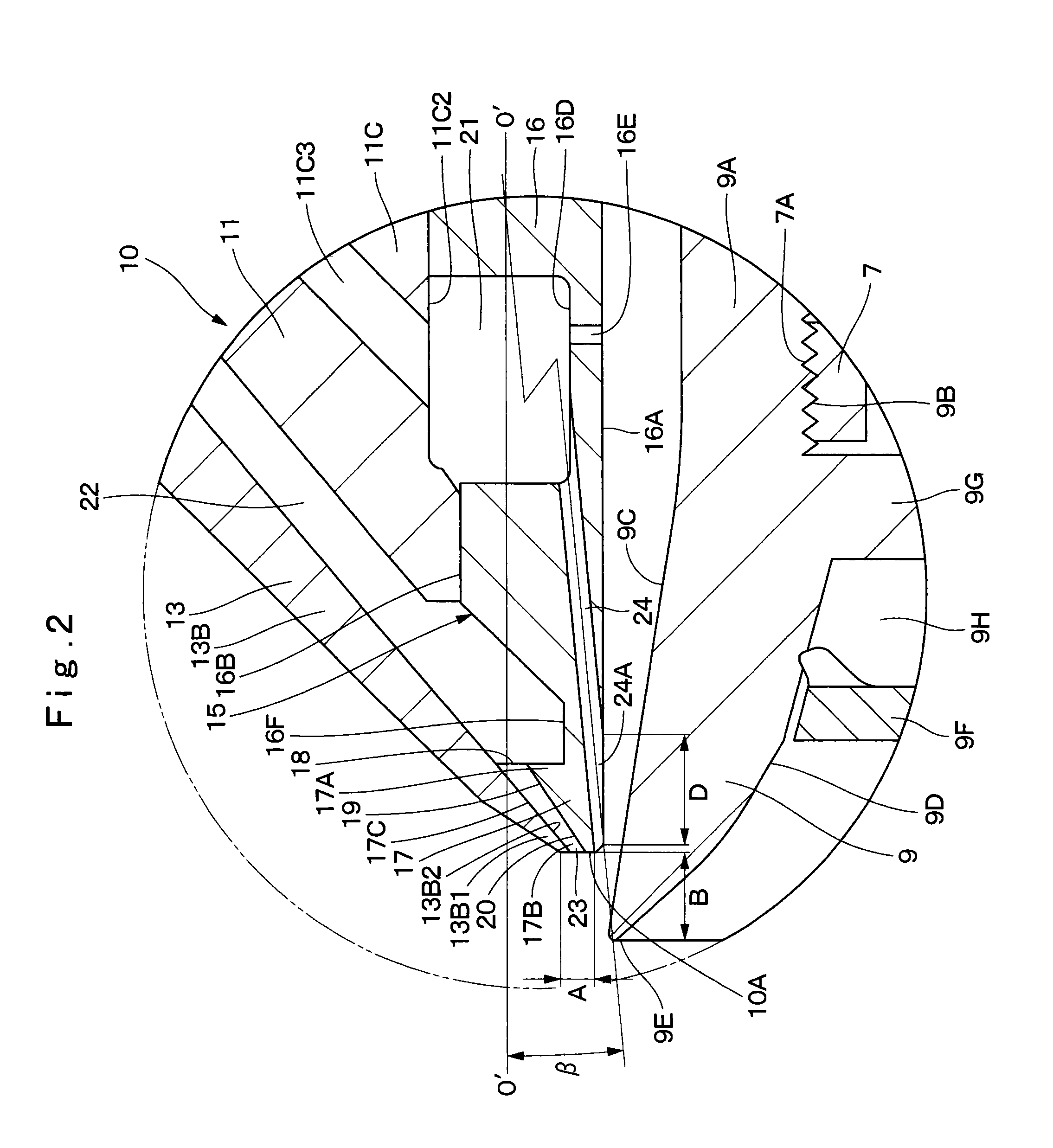
[0031](9) According to the present invention, a radial dimension of the edge-shaped front end surface in the shaping air ring is set to 1 to 6 mm. Therefore, an annular area formed on the front end surface of the shaping air ring can be made as small as possible. Accordingly, since the front end surface positioned in a negative pressure region is made extremely small, the paint is difficult to attach to the front end surface, and even when the paint attaches thereto, the attached paint can be easily washed.
[0032](10) According, to the present invention, a height dimension of each of the side wall surfaces in front ends of the protruding walls respectively is set to 0.4 to 0.6 mm, and a width dimension of each of the groove bottom faces is set to 0.6 to 1.2 mm. Therefore, the first shaping air ejecting hole can be formed as a microscopic hole that is easily processed and washed, and is small in air consumption amount.

Problems solved by technology

Therefore, the structure of the rotary atomizing head type coating machine according to Patent Document 2 has a problem that the paint cannot be micronized and controllability of the spray pattern also deteriorates.

Method used


Image

  • Rotary atomizing head type coating machine
  • Rotary atomizing head type coating machine
  • Rotary atomizing head type coating machine

Examples


Embodiment Construction

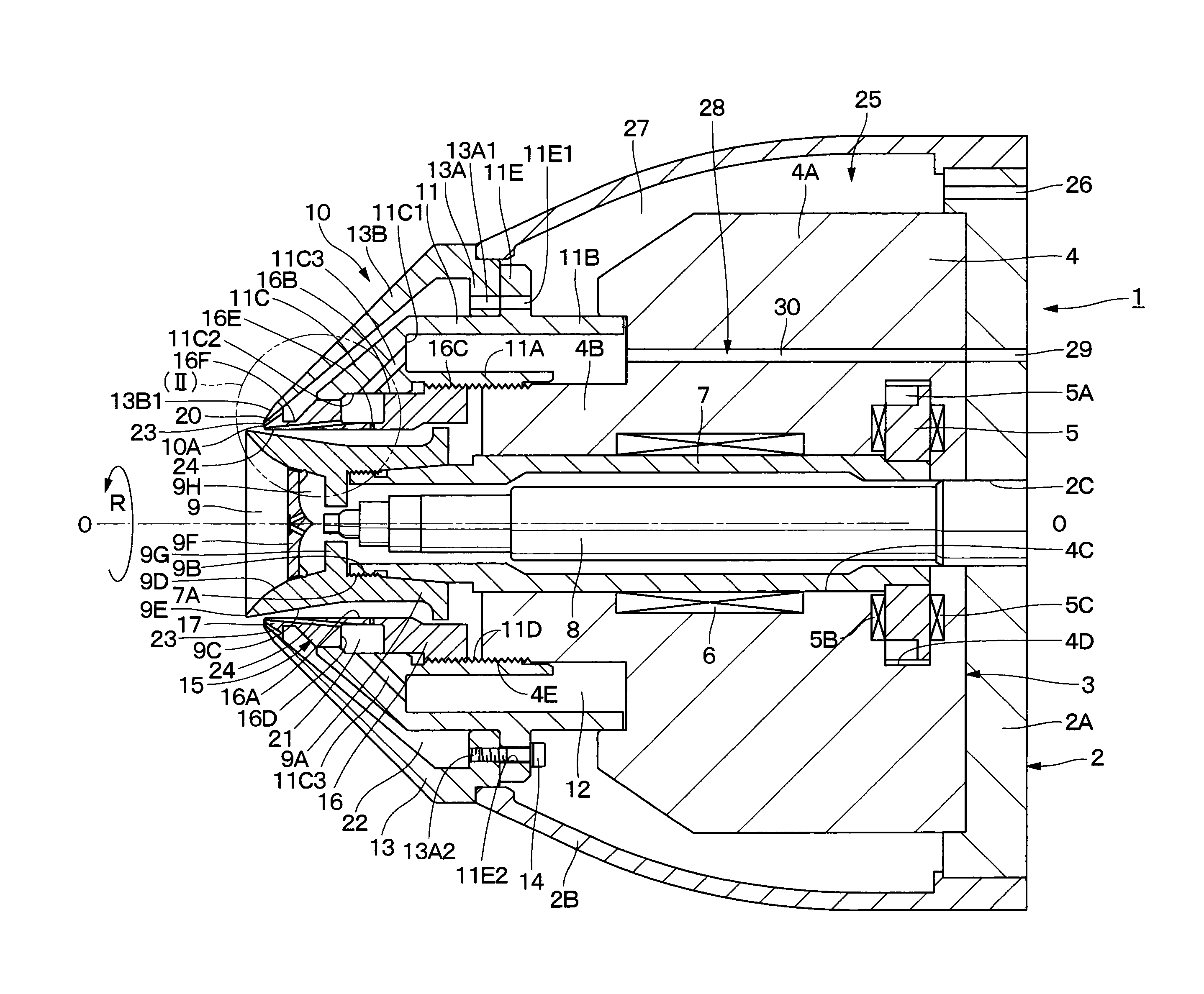
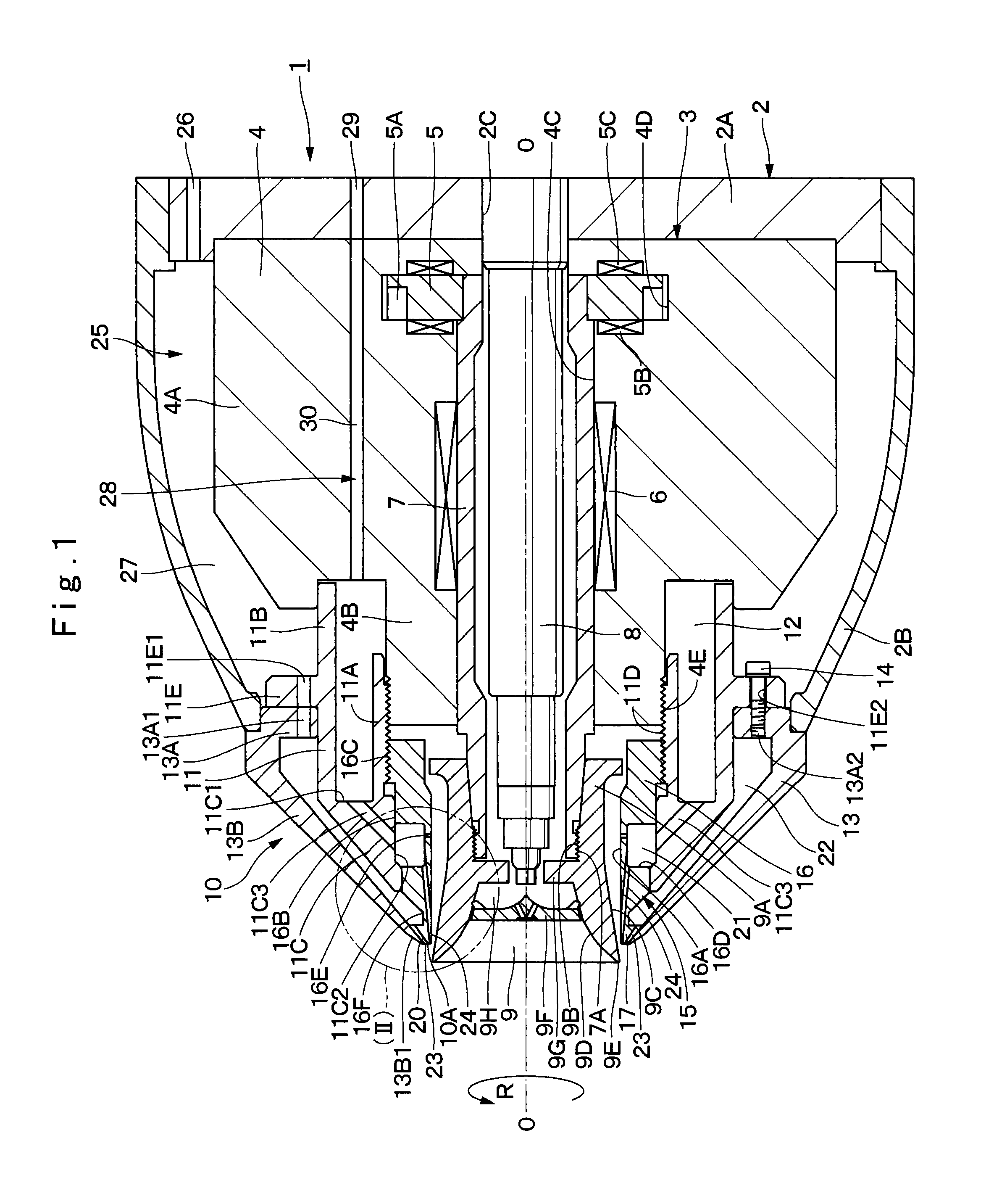
[0042]Hereinafter, a rotary atomizing head type coating machine according to an embodiment of the present invention will be in detail explained with reference to FIG. 1 to FIG. 9. Here, rotary atomizing head type coating machines include two types of coating machines, that is, an electrostatic coating machine that applies high voltages to spraying paint for coating and a non-electrostatic coating machine that does not apply high voltages to paint for coating. The present embodiment as hereinafter described will be explained by taking a rotary atomizing head type coating machine configured as a direct charging type of electrostatic coating machine that applies high voltages directly to paint, as an example.

[0043]In FIG. 1, designated at 1 is a rotary atomizing head type coating machine according to the present embodiment. The rotary atomizing head type coating machine 1 is formed as a direct charging type of electrostatic coating machine that directly applies high voltages to paint b...


PUM


Abstract

A shaping air ring (10) is configured of a body (11), a cover (13) and a nozzle (15). A tapered conical protrusion (17) is provided in a front end of the nozzle (15) to abut on the cover (13) in contact therewith without a clearance therebetween. Numerous inclined recessed grooves (20) are provided on a forward tapered surfaces (17C) of the conical protrusion (17) over the entire periphery. Further, a first shaping air ejecting hole (23) is formed between each of the inclined recessed grooves (20) and an inner peripheral surface (13B2) of the cover (13) to eject shaping air toward a releasing edge (9E) of a rotary atomizing head (9). Second shaping air ejecting holes (24) are provided on an inner peripheral surface (16A) of the nozzle (15) to eject shaping air along an outer peripheral surface (9C) of the rotary atomizing head (9).

Description

TECHNICAL FIELD[0001]The present invention relates to a rotary atomizing head type coating machine provided with a shaping air ring that ejects shaping air to adjust a spray pattern of paint particles sprayed from a rotary atomizing head, for example.BACKGROUND ART[0002]In general, in a case of coating vehicle bodies of automobiles, articles of furniture, electrical appliances, and the like with paint, a rotary atomizing head type coating machine that is excellent in a coating efficiency and coating finish of paint is used. An example of the rotary atomizing head type coating machine includes an electrostatic coating machine that applies high voltages to paint to be supplied to a rotary atomizing head. In this example, paint particles charged with the high voltage can fly along an electrical line of force formed between a coated object and the rotary atomizing head, being efficiently applied on the coated object.[0003]This rotary atomizing head type coating machine is configured of ...

Claims


Application Information

Patent Timeline
Patent Type & Authority Applications(United States)
IPC IPC(8): B05B15/04B05B3/10
CPCB05B3/1035B05B3/1092B05B15/0431B05B5/043B05B5/0415B05B5/0426B05B3/1064
Inventor YAMAUCHI, KUNIHARU
Owner ABB (SCHWEIZ) AG
Why Eureka
Try Eureka