Uniflow scavenging 2-cycle engine

Active Publication Date: 2016-03-03
IHI CORP
View PDF4 Cites 2 Cited by
  • Summary
  • Abstract
  • Description
  • Claims
  • Application Information

AI Technical Summary

Benefits of technology

[0009]According to the uniflow scavenging 2-cycle engine of the present disclosure, since the fuel injection unit is provided so that its injection port is located on the outside of the cylinder, a co

Problems solved by technology

In such a uniflow scavenging 2-cycle engine, when the mixing between the fuel gas and the active gas is insufficient, the c

Method used


Image

  • Uniflow scavenging 2-cycle engine
  • Uniflow scavenging 2-cycle engine
  • Uniflow scavenging 2-cycle engine

Examples


first embodiment

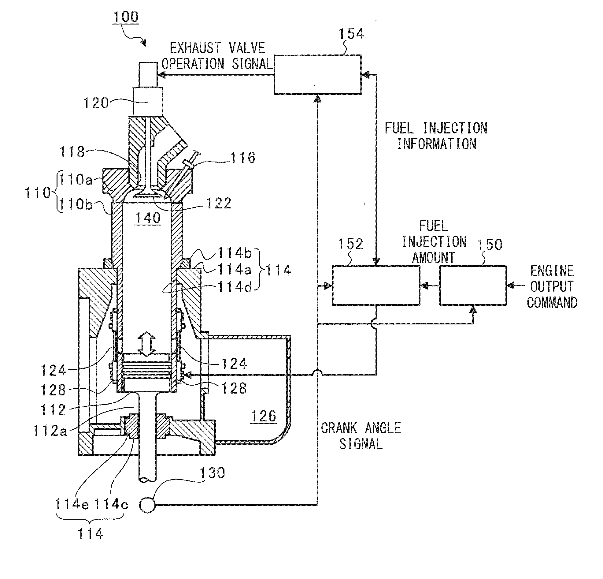
[0018]FIG. 1 is a diagram illustrating an overall configuration of a uniflow scavenging 2-cycle engine 100 in a first embodiment of the present disclosure. The uniflow scavenging 2-cycle engine 100 of this embodiment, for example, is used in a vessel or the like. Specifically, the uniflow scavenging 2-cycle engine 100 is configured to include a cylinder 110 (a cylinder head 110a and a cylinder block 110b), a piston 112, a support unit 114, a pilot injection valve 116, an exhaust port 118, an exhaust valve driving device 120, an exhaust valve 122, a scavenge port 124, a scavenge chamber 126, a fuel injection unit 128, a rotary encoder 130 and a combustion chamber 140. The uniflow scavenging 2-cycle engine 100 is controlled by a control unit, such as a governor (a speed governor 150), a fuel injection control unit 152 and an exhaust control unit 154.

[0019]In the uniflow scavenging 2-cycle engine 100, the piston 112 connected to a crosshead (not illustrated) slidably reciprocates insid...

second embodiment

[0050]Hereinafter, a second fuel injection unit 228 and its support structure in a second embodiment of the present disclosure will be described. Since the second embodiment is different from the first embodiment only in the fuel injection unit 228 and its support structure, here, the same configuration as the first embodiment will not be described, and only the fuel injection unit 228 and its support structure of the different configuration will be described.

[0051]FIG. 4 is an explanatory diagram for describing a uniflow scavenging 2-cycle engine 200 of the second embodiment. In FIG. 4, of the structure of the uniflow scavenging 2-cycle engine 200, functional units of a control system, configurations above the cylinder block 110b, and the scavenge chamber 126 are not illustrated.

[0052]Although the fuel injection unit 228 has substantially the same configuration as the fuel injection unit 128 in the first embodiment, a mixing tube 228a and a mixing tube (pipe unit) 228b into which t...


PUM


Abstract

A uniflow scavenging 2-cycle engine includes a cylinder inside which a combustion chamber is formed; a piston which slides within the cylinder; a scavenge port which is provided on one end side in a stroke direction of the piston in the cylinder to suck an active gas into the combustion chamber in accordance with the sliding movement of the piston; and a fuel injection unit which has an injection port located on the outside of the cylinder, and injects the fuel gas into the active gas sucked into the scavenge port.

Description

[0001]This application is a continuation application based on a PCT Patent Application No. PCT / JP2014 / 062453, filed on May 9, 2014, whose priority is claimed on Japanese Patent Application No. 2013-100529, filed on May 10, 2013. The contents of both the PCT Application and the Japanese Application are incorporated herein by reference.TECHNICAL FIELD[0002]The present disclosure relates to a uniflow scavenging 2-cycle engine which combusts a premixed gas generated by injecting a fuel gas into an active gas sucked from a scavenge port.BACKGROUND ART[0003]In a uniflow scavenging 2-cycle engine (a 2-stroke engine) which is also used as an engine of a vessel, a scavenge port is provided in an end portion in a stroke direction of a piston of a cylinder, and an exhaust port is provided on the other end portion side in the stroke direction of the piston of the cylinder. When an active gas is sucked into a combustion chamber from the scavenge port in an intake (air supply) stroke, the exhaust...

Claims


Application Information

Patent Timeline
IPC IPC(8): F02B25/04F02B75/02F02M21/02
CPCF02B25/04F02B2075/025F02M21/0278F02B75/02F02M21/042F02D19/0647F02D19/10Y02T10/36Y02T10/32Y02T10/30
Inventor KUGE, TAKAHIROMASUDA, YUTAKAYAMADA, TAKAYUKIYAMADA, TAKESHI
Owner IHI CORP
Why Eureka
Try Eureka