A system and method for optimizing fiducial marker and camera positions/orientations

Active Publication Date: 2016-03-03
ASELSAN ELEKTRONIK SANAYI & TICARET ANONIM SIRKETI
View PDF3 Cites 11 Cited by
  • Summary
  • Abstract
  • Description
  • Claims
  • Application Information

AI Technical Summary

Problems solved by technology

This method is intended to be used in large areas with fiduciary marks and can not be applied to optimize fiducial locations on a moving tracked object being captured by a stationary camera.
Furthermore, the pose estimation parameters used by the pose estimation algorithm are not considered in the current methods, which directly affect the output accuracy of the system.
However, this method greedily tries to

Method used


Image

  • A system and method for optimizing fiducial marker and camera positions/orientations
  • A system and method for optimizing fiducial marker and camera positions/orientations
  • A system and method for optimizing fiducial marker and camera positions/orientations

Examples


Embodiment Construction

[0014]A system and method realized to fulfill the objective of the present invention is illustrated in the accompanying figures.

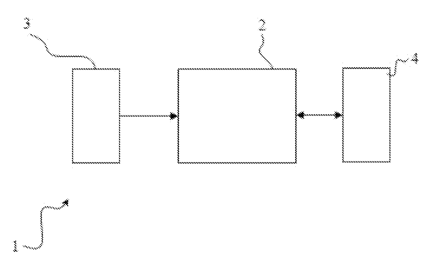
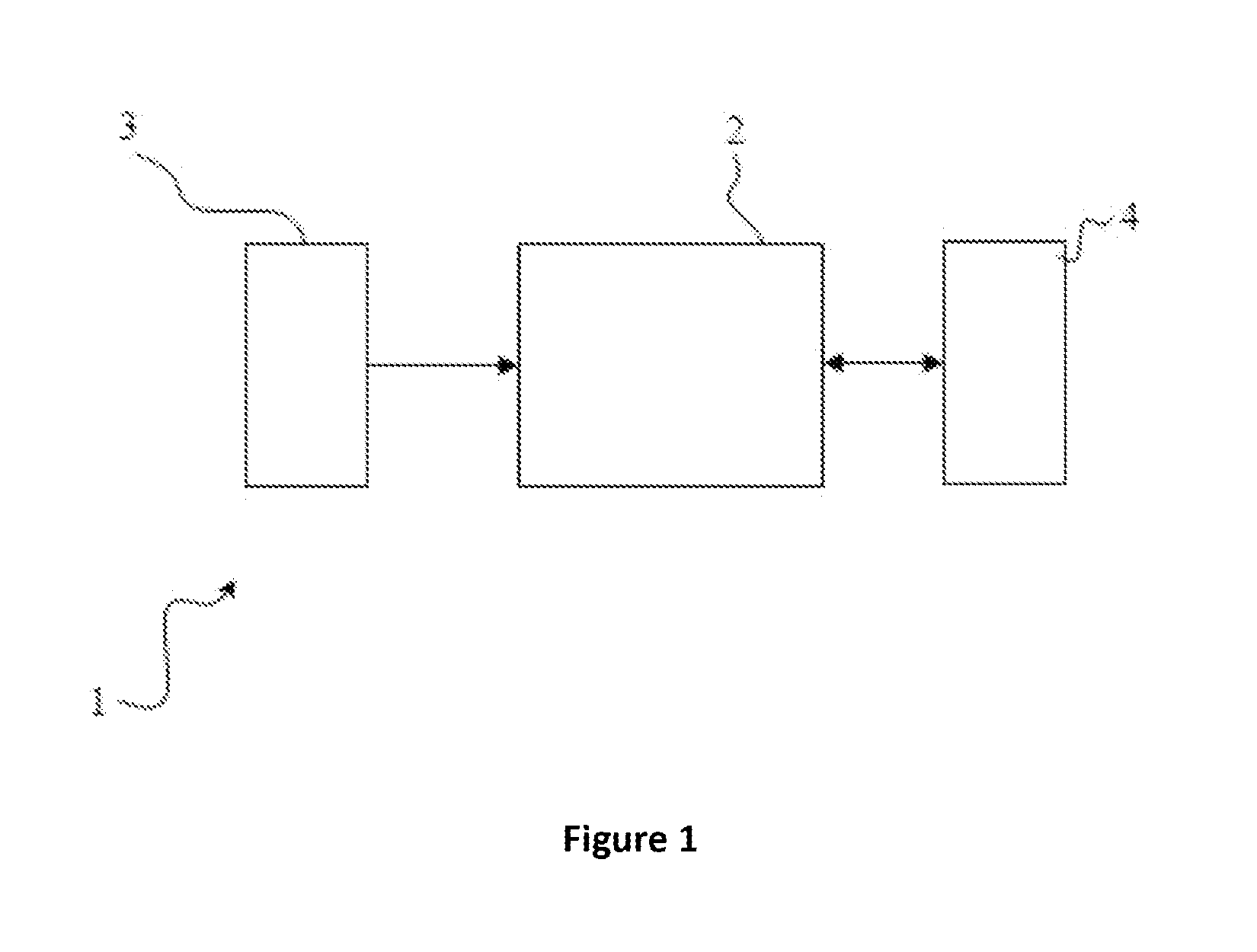
[0015]The components illustrated in the figures are individually referenced where the numbers and letters refer to the following:

1. System for optimizing tracker system

2. Processing unit

3. Input / output device

4. Memory unit

100. Method for optimizing fiducial marker positions and orientations.

200. Method for optimizing fiducial marker and camera positions / orientations.

[0016]Throughout the remaining parts of the specifications, finding the position and orientation of a special object (fiducial marker or camera) in the configuration will be referred to as placement of that special object.

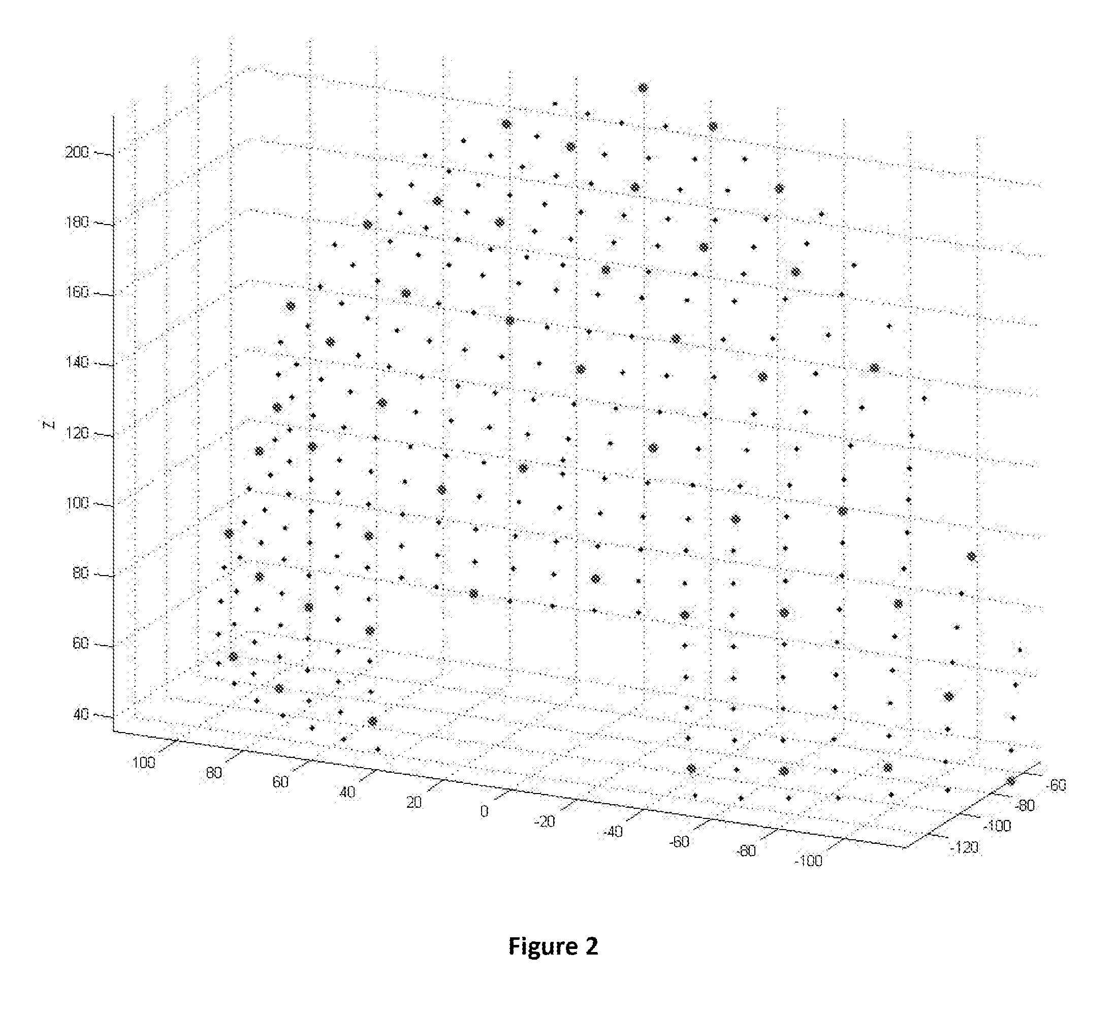
[0017]A method for optimizing fiducial marker positions and orientations (100) essentially comprises the steps of,[0018]acquiring mesh data representing possible active marker positions and feasible orientation boundaries of markers on a tracked object; pose data representing p...


PUM


Abstract

A method for optimizing fiducial marker and camera positions/orientations is realized to simulate camera and fiducial positions and pose estimation algorithm to find best possible marker/camera placement comprises the steps of: acquiring mesh data representing possible camera positions and feasible orientation boundaries of cameras on the environment of tracked object; acquiring mesh data representing possible active marker positions and feasible orientation placements of markers on a tracked object; pose data representing possible poses of tracked object under working conditions; initializing the control parameter for camera placement; create initial solution strings for camera placement; solving marker placement problem for the current camera placement; evaluating the quality of the current LED and camera placement taking pose coverage, pose accuracy, number of placed markers, number of placed camera etc. into account; determining if a stopping criterion is satisfied.

Description

FIELD OF THE INVENTION[0001]The present invention relates to the field of computation and simulation and covers methods to optimize the fiducial marker and camera positions / orientations in optical object tracking systems, by simulating the visibility.BACKGROUND OF THE INVENTION[0002]It is known that there are methods and models to track a three dimensional object in an environment and compute its position and orientation (pose) with respect to a predetermined coordinate system. These kinds of tracker systems are used for example in aircrafts to determine the orientation of head of the pilot. Once the orientation is acquired with respect to the coordinate system of say the display devices, then it is possible to generate graphics on these accordingly. There are different methods to track an object in the scene using magnetic, mechanical or optical means. Currently, the spatial relations of objects may also be determined using magnetic sensors or laser beams but this invention relates...

Claims


Application Information

Patent Timeline
IPC IPC(8): G06T7/00G06T7/20
CPCG06T7/0042G06T2207/10016G06T2200/04G06T7/20G06T2207/30204G06T7/73
Inventor OKUYAN, ERKANYILMAZ, OZGUR
Owner ASELSAN ELEKTRONIK SANAYI & TICARET ANONIM SIRKETI
Why Eureka
Try Eureka