Wire harness

Inactive Publication Date: 2016-03-03
SUMITOMO WIRING SYST LTD
View PDF4 Cites 10 Cited by
  • Summary
  • Abstract
  • Description
  • Claims
  • Application Information

AI Technical Summary

Benefits of technology

[0016]With this configuration, conductors for three channels can be provided in substantially one wire, thereby reducing the number of wires, which makes it even easier to handle the first to third wires and is further advantageous for weight reduction and cost reducti

Problems solved by technology

However, in conventional wire harnesses in which the wire group is surrounded by a shielding material and an outer material for sheathing, the wire bundle at the wiring segment that is to be shielded is covered by overlaying a shielding material such as a braided wire shielding material or a spiral winding shielding material and an outer material for sheathing thereon, and therefore, in addition to the winding task being time-consuming, the wire harness is bulky, and it is not possible to sufficiently meet the requirements of weight reduction and cost reduction in the wire harness.
Also, if the wiring segment to be shielded takes up a large range, these problems are exacerbated.
In particular, with a wire harness including wires used in a transistor input/output circuit, the above-described problems are fu

Method used


Image

  • Wire harness
  • Wire harness
  • Wire harness

Examples


embodiment

[0026]FIGS. 1A-6D show a wire harness W according to an embodiment of the present invention.

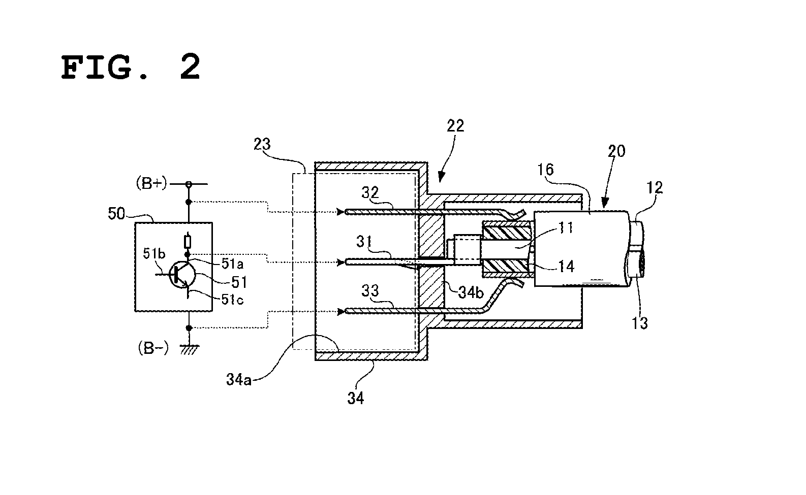
[0027]Note that the wire harness W in the present embodiment is a unit obtained by mounting a connector, terminals, and the like to a wire group 1 composed of multiple wires, and is configured to be able to connect an electrical device mounted in a vehicle to a power supply, a control device, or the like.

[0028]The wire group 1 of the wire harness W has flexibility, which allows it to be arranged on a predetermined arrangement path on a vehicle panel (not shown), and a shielded segment at which a shield for electromagnetic shielding or the like is required is set at a position on the arrangement path.

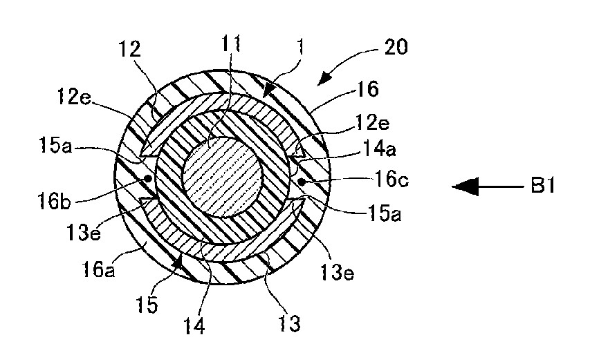
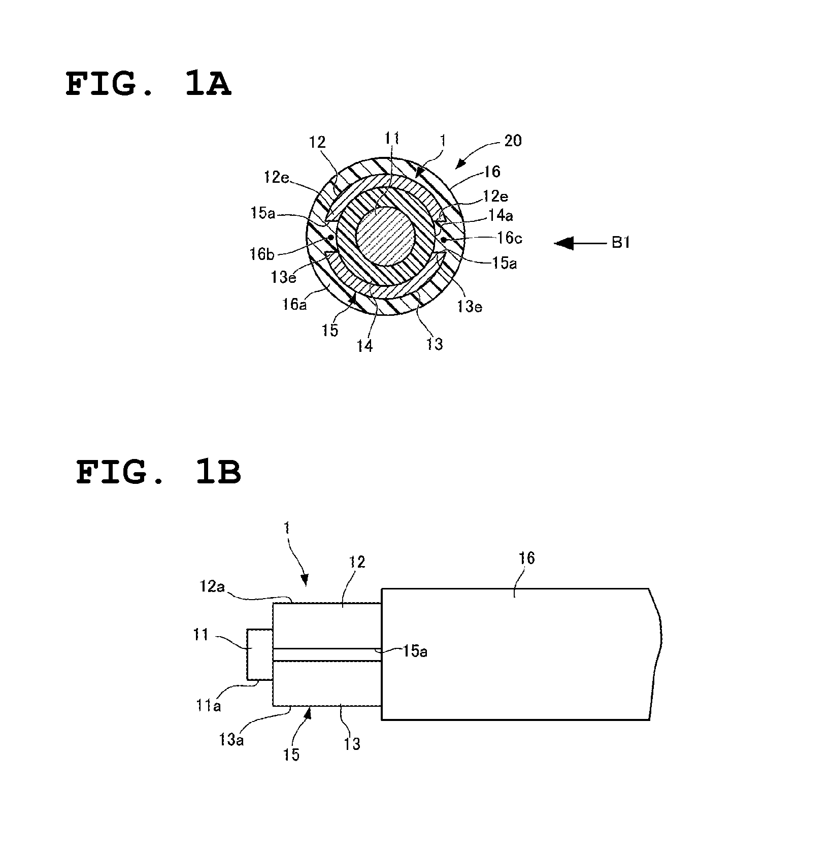
[0029]As shown in FIGS. 1A and 1B, the wire harness W includes a wire group 1 including at least a first wire 11, a second wire 12, and a third wire 13, and includes a retaining member (to be described in detail later) that surrounds the wire group 1 such that the wire group is retained in the for...


PUM


Abstract

Provided is a wire harness having a shielding structure that can achieve a required shielding effect while sufficiently meeting the requirements of weight reduction and cost reduction. The wire harness includes a wire group constituted by a plurality of wires and a retaining member that surrounds the wire group such that the wire group is retained in the form of a bundle, wherein the wire group is configured to include a first wire composed of a linear conductor that is located toward the center of the wire group, a tube-shaped wire sheathing that surrounds the first wire, and a second wire and a third wire that are composed of an opposing pair of split tube-shaped conductors that are insulated from each other with the first wire and the wire sheathing being interposed therebetween.

Description

TECHNICAL FIELD[0001]The present invention relates to a wire harness, and in particular relates to a wire harness having an electromagnetic shielding structure that is suitable when used in a transistor input / output circuit, or the like.BACKGROUND ART[0002]Conventionally, a wire shielding structure in which a wire group in the segment to be shielded is wrapped in a braided wire shielding material, a spiral winding shielding material, aluminum foil, or the like, and is surrounded from the outside by an outer member for sheathing is frequently used in the case of performing shielding (electromagnetic shielding, or the like) on a wire group in a wire harness in a predetermined wiring segment (e.g., see JP H10-125138A and JP 2009-93934A).[0003]Also, there are known to be electrical wires in which a conducting layer and an insulating layer that surrounds the conducting layer are formed on the outer circumferential surface of an inner non-metallic linear member in the interest of obtainin...

Claims


Application Information

Patent Timeline
IPC IPC(8): H01B9/02H01B7/00
CPCH01B7/0045H01B9/02H01B7/0018H01R9/0527H01R24/30H01R2103/00
Inventor WAKABAYASHI, MASATAKAFUKUDA, MINORU
Owner SUMITOMO WIRING SYST LTD
Why Eureka
Try Eureka