Keyswitch structure

a keyswitch and structure technology, applied in the direction of emergency actuators, contact fixing to operating parts, contact mechanisms, etc., can solve the problems of complication and difficulty in assembly, and achieve the effect of reducing the overall thickness of the keyswitch structure and the number of components

Active Publication Date: 2016-03-03
DARFON ELECTRONICS CORP
View PDF2 Cites 8 Cited by
  • Summary
  • Abstract
  • Description
  • Claims
  • Application Information

AI Technical Summary

Benefits of technology

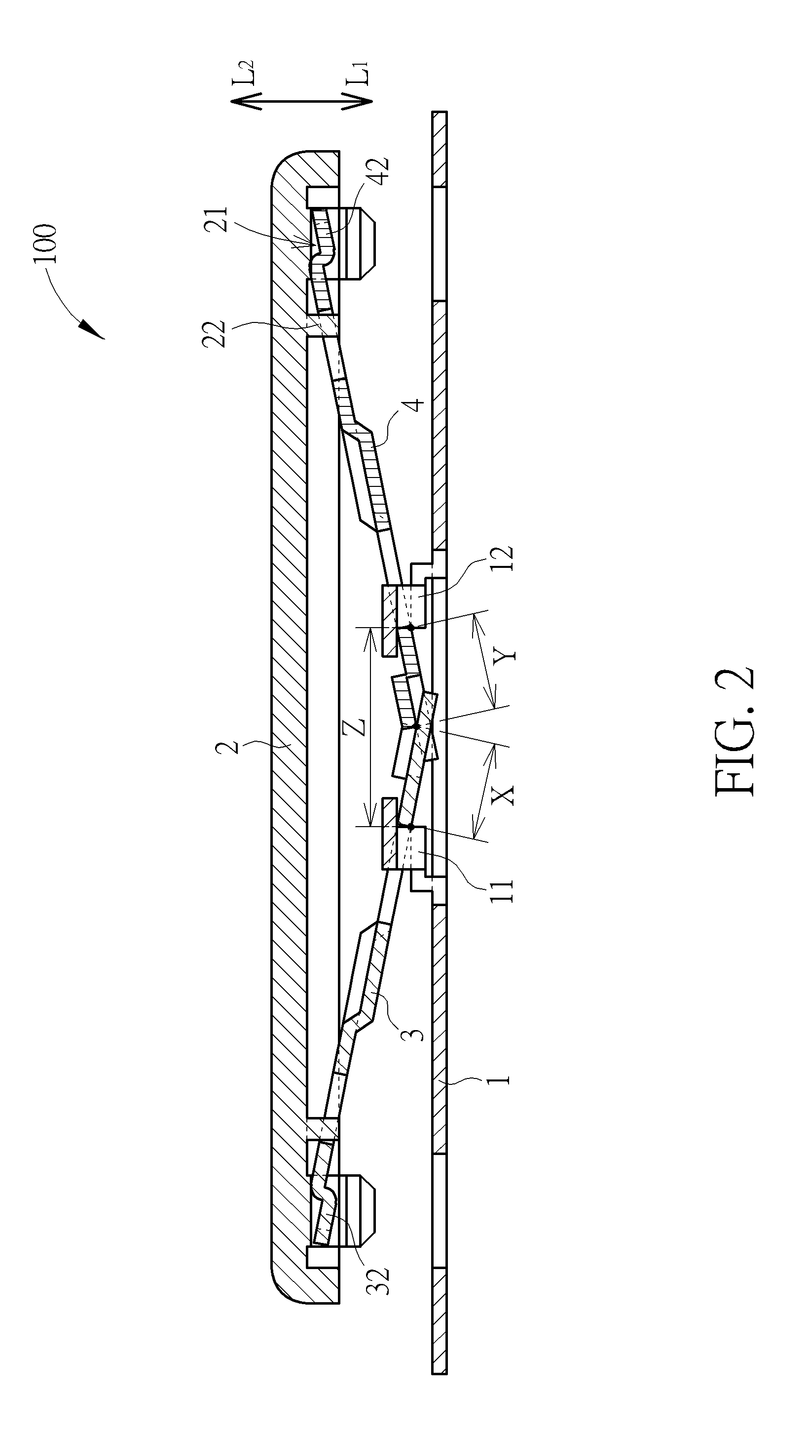
[0016]With the structure provided in the invention, no further resilient member is required for providing the resilient restoring force. Besides, the virtual axes formed by line contacting bet

Problems solved by technology

However, such scissor structure takes up more than a few conjunctions of compo

Method used


Image

  • Keyswitch structure
  • Keyswitch structure
  • Keyswitch structure

Examples


Embodiment Construction

[0027]Certain terms are used throughout the description and following claims to refer to particular components. As one skilled in the art will understand, electronic equipment manufacturers may refer to a component by different names. This document does not intend to distinguish between components that differ in name but not function. In the following description and in the claims, the terms “include” and “comprise” are used in an open-ended fashion, and thus should be interpreted to mean “include, but not limited to . . . . ” In addition, to simplify the descriptions and make it more convenient to compare between each embodiment, identical components are marked with the same reference numerals in each of the following embodiments. Please note that the figures are only for illustration and the figures may not be to scale.

[0028]Also, the term “couple” is intended to mean either an indirect or direct electrical / mechanical connection. Thus, if a first device is coupled to a second devi...


PUM


Abstract

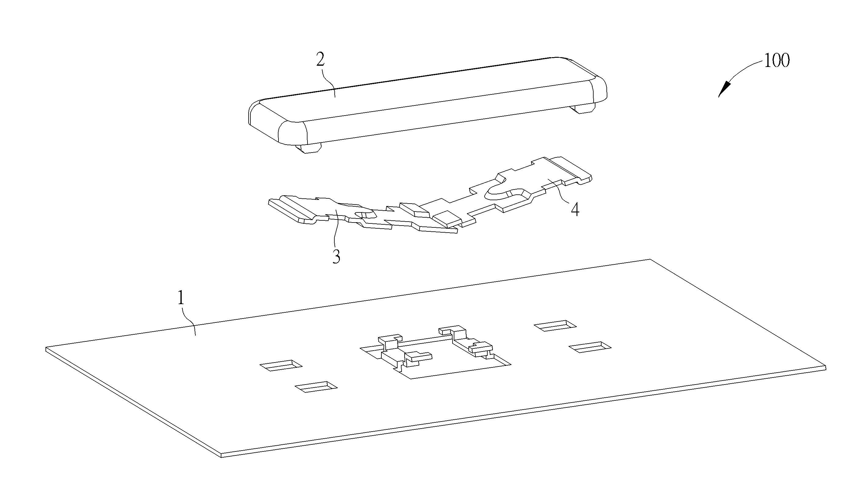
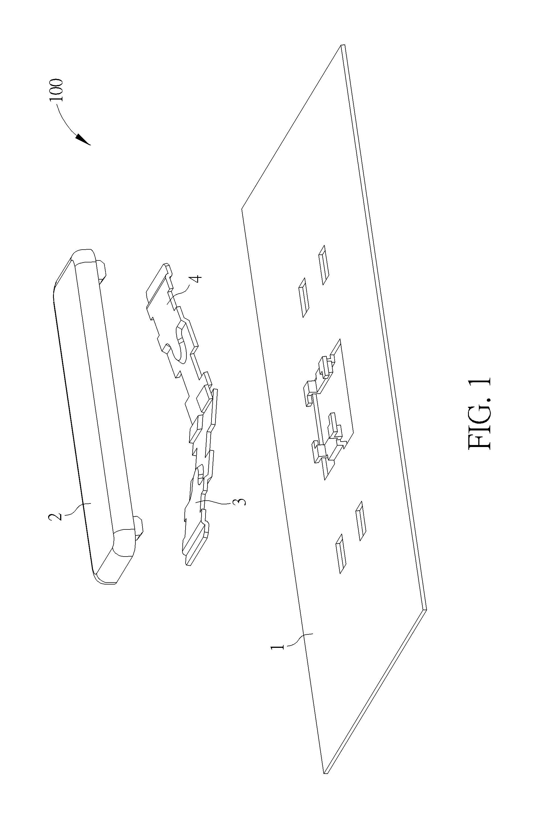
The keyswitch structure uses two linkages form as V-shaped to support a keycap when the keycap is moved up and down. A first linkage and a second linkage are coupled with each other and also coupled with a support on a base respectively in a line contacting way, thereby forming a first axis, a second axis, and a third axis. The third axis is located between the first axis and the second axis. As the keycap is pressed to move downward, the keycap brings the two linkages and the support of the base to have relative rotation movement. Due to the geometric feature between the three axes, part of the linkages between the axes or the support of the base may be caused to slightly deform to provide a resilient restoring force that can move the keycap upward to a position not being pressed.

Description

BACKGROUND OF THE INVENTION[0001]1. Field of the Invention[0002]The present invention relates to a keyswitch structure, and more particularly, to a keyswitch structure having a linkage device with virtual axes.[0003]2. Description of the Prior Art[0004]Keyboards are one of the necessary input apparatuses for inputting letters, symbols, or numbers when it comes to using a personal computer. Besides, both consumer electronic devices in our daily life or large machining equipment used for industry need keyswitch structure as the inputting apparatus in order to be operated or controlled.[0005]A keyswitch structure in the prior art may primarily include a base, a keycap, and a lifting supporting device that connects the base and the keycap. As the keycap is supposed to be steady when moving up and down to properly function as pressing and activating a switch, a scissor structure is usually adapted as the supporting device. However, such scissor structure takes up more than a few conjunct...

Claims


Application Information

Patent Timeline
IPC IPC(8): H01H13/14
CPCH01H2205/002H01H13/14H01H3/122H01H2221/024H01H2227/036H01H2235/00
Inventor CHAO, LING-HSI
Owner DARFON ELECTRONICS CORP
Why Eureka
Try Eureka