

Image sensor and operating method thereof, motion sensor including the same
- Summary
- Abstract
- Description
- Claims
- Application Information
AI Technical Summary
Benefits of technology
Problems solved by technology
Method used
Image

Examples
first embodiment
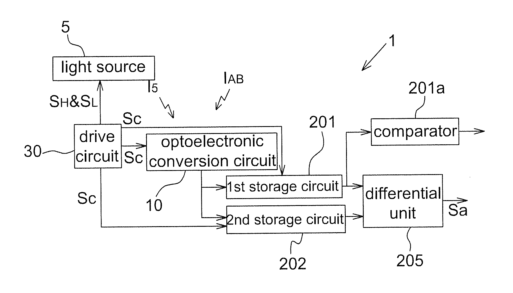
[0045]FIG. 3 is a flow chart of an operating method of an image sensor according to the present disclosure. The image sensor includes an optoelectronic element, a pixel buffer circuit, a first storage circuit, a second storage circuit and a differential unit. The first storage circuit and the second storage circuit are respectively coupled to two input terminals of the differential unit. The optoelectronic element is configured to generate photocurrents to be stored in the pixel buffer circuit corresponding to a high level signal and a low level signal, wherein the high level signal and the low level signal are configured to turn on and turn off a light source. The operating method includes the steps of: storing a first charge from the optoelectronic element to the pixel buffer circuit in a period of the high level signal (Step S1); transferring the first charge in the pixel buffer circuit to the first storage circuit in a period of the low level signal (Step S2); storing a second c...
second embodiment
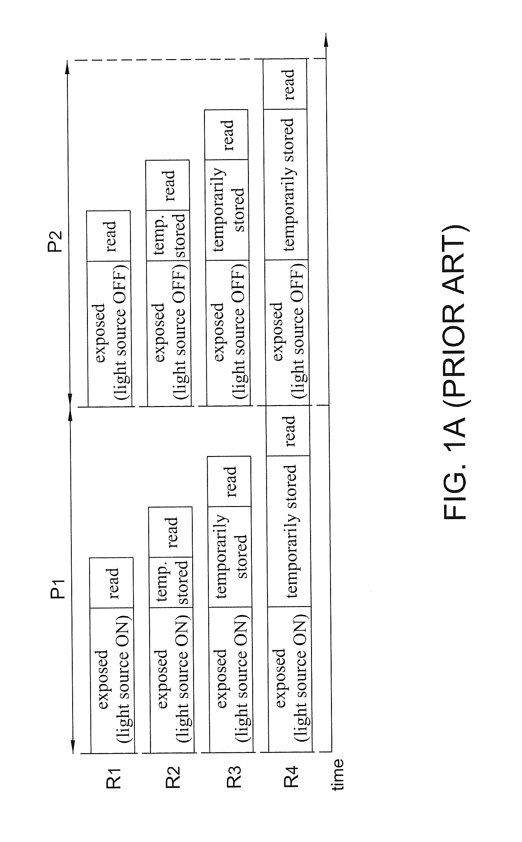
[0076]In the second embodiment, each of the optoelectronic conversion circuits 10 is configured to store a first charge Q1 corresponding to a first exposure period and store the first charge Q1 for a storing period, successively output the first charge Q1 (e.g. to the bit line 70) and store a second charge Q2 corresponding to a second exposure period, and output the second charge Q2 (e.g. to the bit line 70), wherein the storing period is between the first exposure period and the second exposure period as shown in FIG. 8.
[0077]In this embodiment, as the image sensor 1 is a rolling shutter image sensor, a start time of the first exposure period (e.g. a time turning off the fifth gate 108) of every row of sensing pixels (e.g. R1 to R4 in FIG. 8) has a row delay time from each other. The operations of every row of sensing pixels are identical except with the row delay time. Accordingly, the storing periods o f every row of sensing pixels are identical. Since the second embodiment is ap...
PUM
 Abstract
Description
Claims
Application Information