
Combined center cam and reel arm

a center cam and reel arm technology, applied in the field of combined center cam and reel arm, can solve the problems of certain crops being prone to improper flow near the outboard end of the crop reel, and achieve the effect of reducing the number of crop reels

Active Publication Date: 2016-03-10
BLUE LEAF I P
View PDF9 Cites 9 Cited by
  • Summary
  • Abstract
  • Description
  • Claims
  • Application Information

AI Technical Summary

Benefits of technology

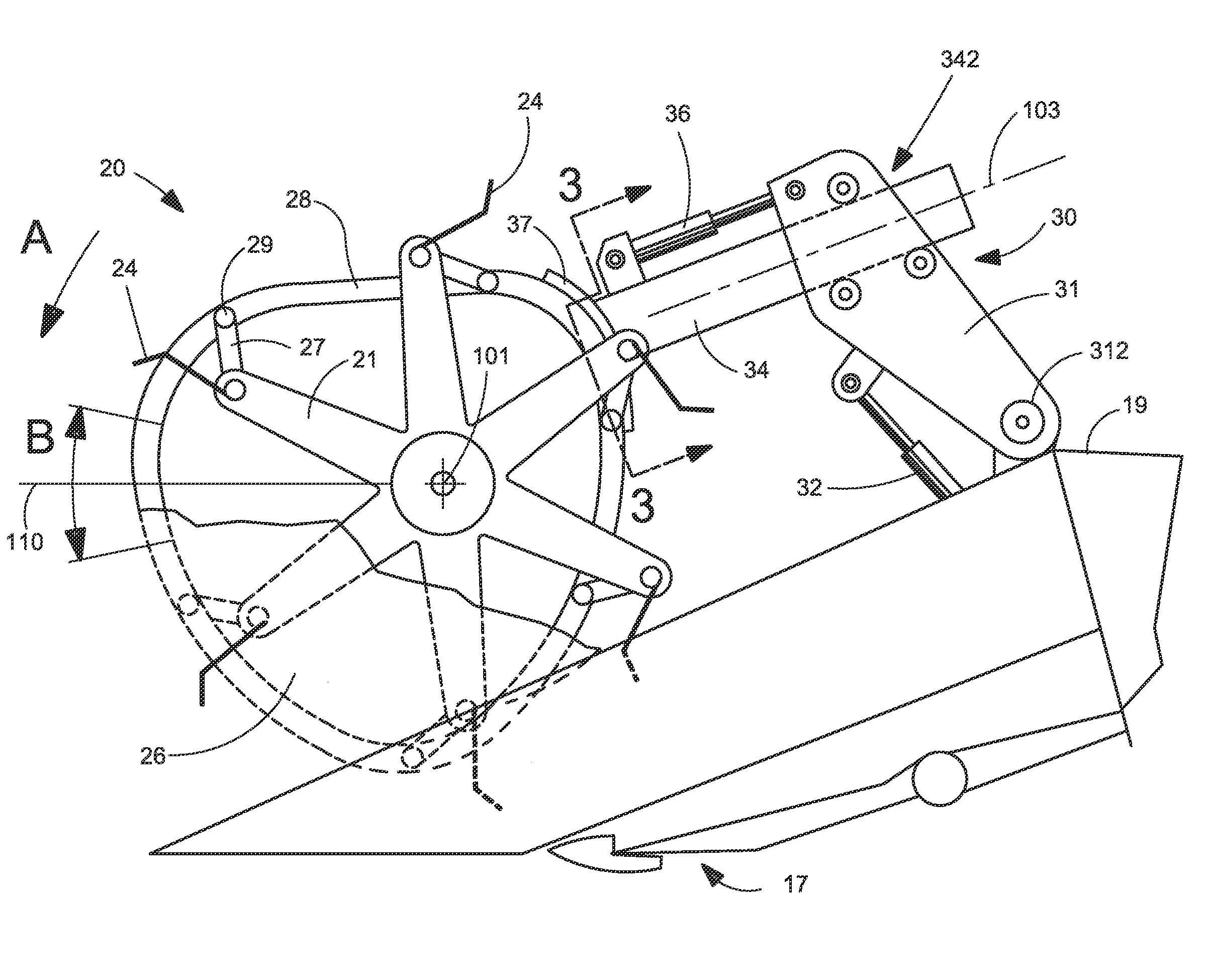
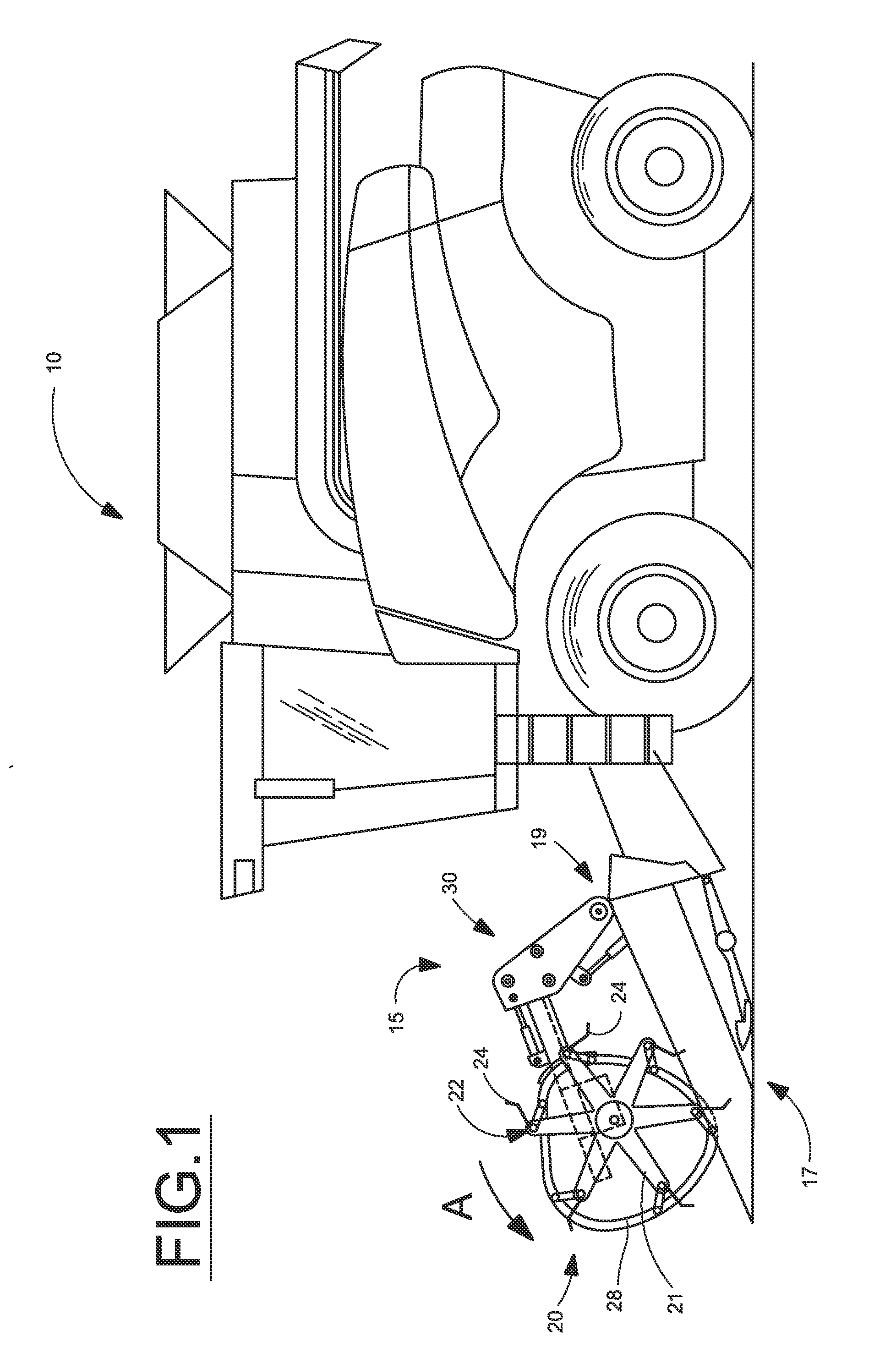
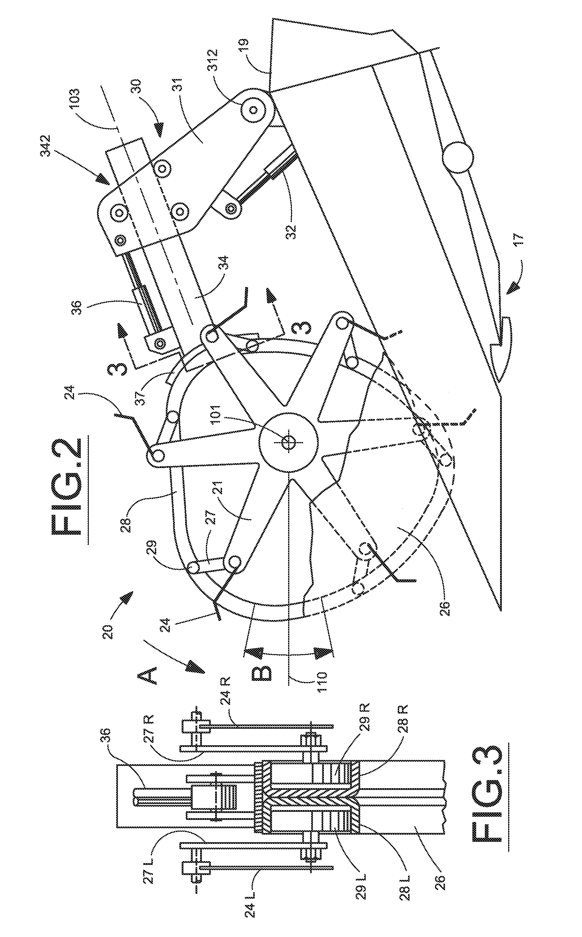
The present invention provides an integrated reel arm and reel cam for use in an agricultural harvesting header that reduces the width of the integrated assembly. The reel arm and cam are positioned within the same lateral space, allowing for a narrower reel assembly. The reel arm can also be adjusted for cam timing and is durable, inexpensive, and easy to assemble and use. This design may also benefit conventional outboard reel cam configurations by reducing the space requirements at the ends of a header reel.

Problems solved by technology

Experience with some crop harvesting headers shows that certain crops are prone to improper flow near the outboard ends of the crop reel due to interaction with the cam and the reel arm.

Method used


Image

  • Combined center cam and reel arm
  • Combined center cam and reel arm
  • Combined center cam and reel arm

Examples


Embodiment Construction

)

[0017]Many of the fastening, connection, processes and other means and components utilized in this invention are widely known and used in the field of the invention described, and their exact nature or type is not necessary for an understanding and use of the invention by a person skilled in the art, and they will not therefore be discussed in significant detail. Also, any reference herein to the terms “left” or “right” are used as a matter of mere convenience, and are determined by standing at the rear of the machine facing in its normal direction of travel. Likewise, “forward” and “rearward” are determined by the normal direction of travel. “Upward” and “downward” orientations are relative to the ground or operating surface as are any references to “horizontal” or “vertical” planes. Furthermore, the various components shown or described herein for any specific application of this invention can be varied or altered as anticipated by this invention and the practice of a specific ap...


PUM


Abstract

An integrated reel arm and reel cam for use in an agricultural harvesting header that positions both within the same lateral space in order to reduce the width of the integrated assembly. The reel arm connects directly to a rearwardly facing structure on the reel cam and may include adjustment means for varying cam timing. The lateral width of the reel arm and connection is configured to be no greater than the lateral width of the reel cam thereby enabling positioning of a reel cam between adjacent reels in little more than the lateral width of the cam itself. The integrated reel arm and reel cam may also benefit conventional outboard reel cam configurations by reducing the lateral space requirements at the ends of a header reel.

Description

BACKGROUND OF THE INVENTION[0001]The present invention relates generally to agricultural harvesting machines having crop harvesting headers, such as combines, and, more particularly to harvesting machines having a reel positioned above a cutting mechanism for assisting in feeding of crop material through the harvesting header.[0002]Many harvesting headers employ a rotary reel to assist with crop movement into the cutting mechanism. The reel, including a plurality of tine bars having axially spaced tines therealong, guides the crop material to be harvested towards a cutter bar extending between header sidewalls, and the cut crop is transported on a draper or auger transport arrangement into the harvester for further processing. The tine bars are mounted for pivotal movement about a respective tine bar axis generally parallel to a reel rotational axis. A cam, typically mounted between the sidewall and an end of the rotary reel, in cooperation with linkages to each tine bar, controls t...

Claims


Application Information

Patent Timeline
IPC IPC(8): A01D57/04A01D57/02
CPCA01D57/02A01D57/04
Inventor COOK, JOEL, TIMOTHY
Owner BLUE LEAF I P
Learn More