Control system for power unit

a control system and power unit technology, applied in the direction of electric programme control, program control, instruments, etc., can solve the problems of not taking into account the influence of rotational friction, and the technique described in the patent document 1 does not take into account the springiness of the power

Active Publication Date: 2016-03-10
HONDA MOTOR CO LTD
View PDF5 Cites 8 Cited by
  • Summary
  • Abstract
  • Description
  • Claims
  • Application Information

AI Technical Summary

Benefits of technology

[0040]This arrangement makes it possible to determine the manipulated variable while compensating for the influence of a high-frequency noise component included in an output of ...

Problems solved by technology

However, the power transmission element, including the reduction gear, generally has a certain level of springiness, and the springiness of the power transmission element may give rise to the oscillation phenomenon of the driving force applied to the element to be driven.
However, the technique described in Patent Doc...

Method used


Image

  • Control system for power unit
  • Control system for power unit
  • Control system for power unit

Examples


first embodiment

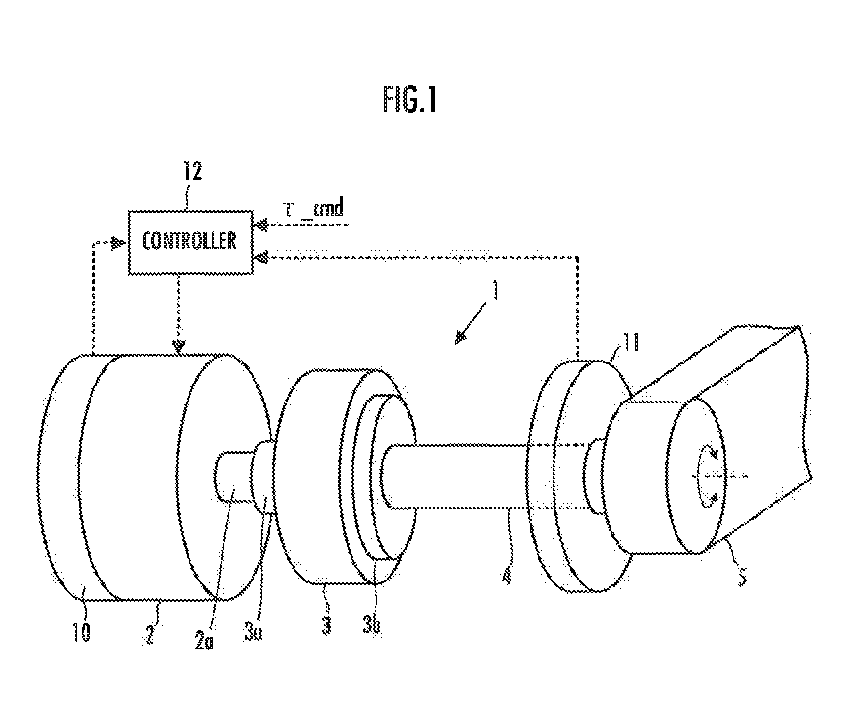
[0046]A first embodiment of the present invention will be described below with reference to FIG. 1 and FIG. 2.

[0047]Referring to FIG. 1, a power unit 1 according to the present embodiment is a unit that rotatively drives a rotary member 5, which functions as an element to be driven, by a driving force of an electric motor 2. In the power unit 1, a power transmission system between the electric motor 2 and the rotary member 5 is provided with a reduction gear 3 and a torsion bar 4.

[0048]The rotary member 5 is, for example, a constituent element of a joint of a robot (a link member rotatable about a joint axis). However, the rotary member 5 may be another member.

[0049]The electric motor 2 corresponds to the actuator in the present invention. The electric motor 2 in the present embodiment is a rotary type actuator that outputs a rotative driving force (torque) from an output shaft 2a serving as an output section thereof

[0050]The reduction gear 3 constitutes the power transmission eleme...

second embodiment

[0109]Referring now to FIG. 3, a second embodiment of the present invention will be described. The present embodiment differs from the first embodiment only partly in the control processing by a controller 12. Hence, the description of the same aspects as those of the first embodiment will be omitted.

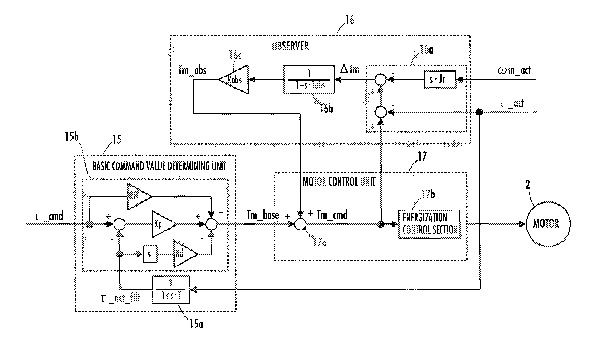
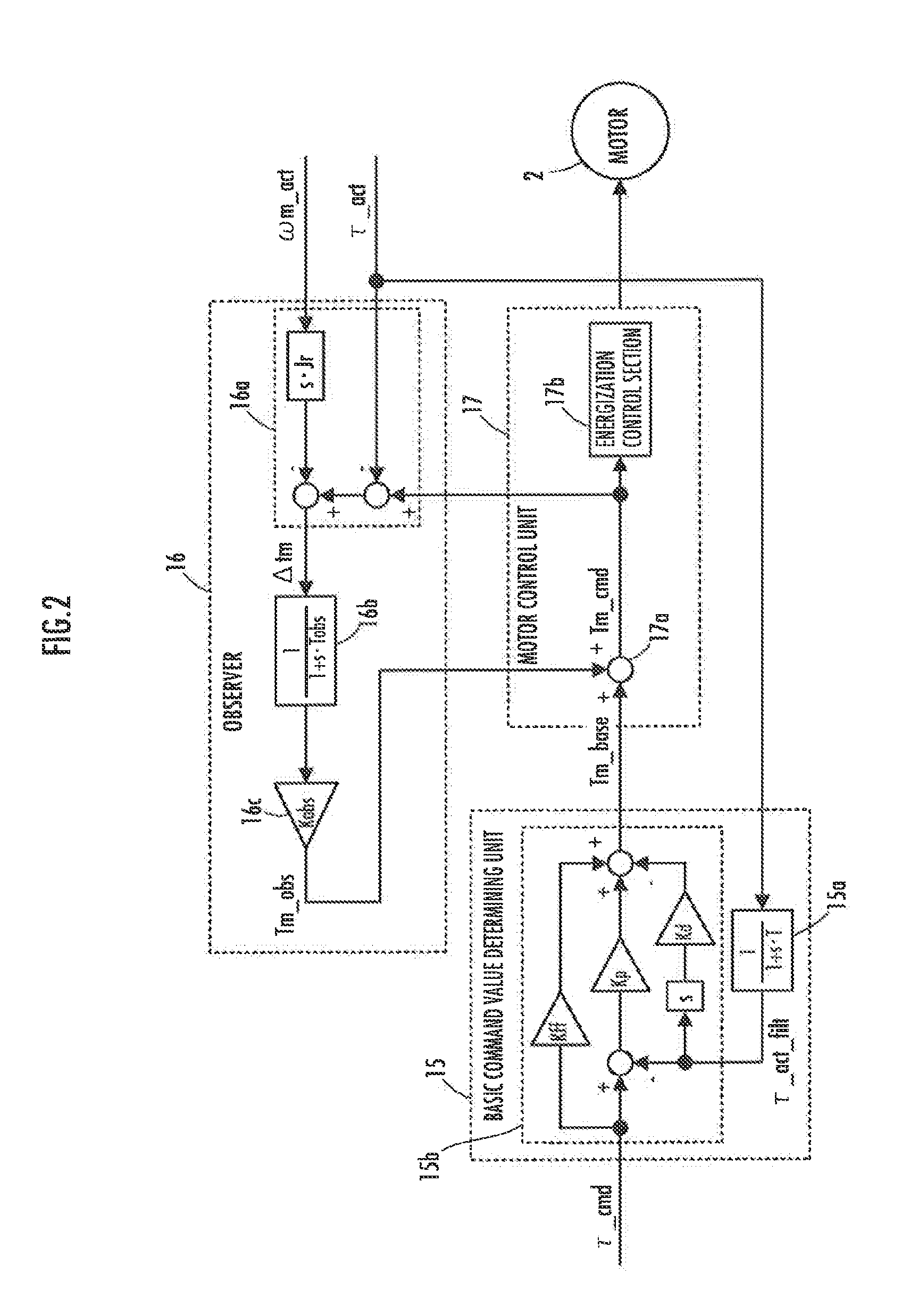
[0110]Referring to FIG. 3, the present embodiment differs from the first embodiment only partly in the processing by an observer 21.

[0111]The observer 21 in the present embodiment carries out the so-called pseudo differential processing to determine a corrective manipulated variable Tm_obs without directly differentiating the detection value of an actual motor rotational velocity ωm_act indicated by an output of a rotation detector 10.

[0112]To be specific, the observer 21 in the present embodiment has a low-pass filter 21b (a filter having the transfer function thereof expressed by 1 / (1+s−Tobs) in the illustrated example), which is the same as that in the first embodiment. Further, the ...


PUM


Abstract

A control system of a power unit in accordance with the present invention corrects a basic command value of an electric motor 2, which has been determined such that the detection value of a driving force to be applied to a rotary member 5 is converged to a desired value, according to a manipulated variable determined by an observer 16. The electric motor 2 is controlled according to a desired control value after the correction. The observer 16 determines the manipulated variable such that the driving force based on the desired control value is brought close to the resultant force of a force indicated by the rotary member 5 and an inertial force.

Description

BACKGROUND OF THE INVENTION[0001]1. Field of the Invention[0002]The present invention relates to a system that controls the driving force imparted from an actuator to an element to be driven, such as a link connected to a joint of a robot.[0003]2. Description of the Related Art[0004]As a power unit that drives a joint mechanism of a robot or the like, there has conventionally been known a power unit in which a spring member is interposed between an output section of an actuator and an element to be driven, such as a joint mechanism, and which is adapted to control the actuator such that the driving force (a translational force or a moment) applied to the element to be driven follows a desired value.[0005]This type of unit is described in, for example, Japanese Patent Application Laid-open No. 2001-195133 (hereinafter referred to as Patent Document 1) or “High-Fidelity Joint Drive System by Torque Feedback Control Using High Precision Linear Encoder / Tomohiro Kawakami, Ko Ayusawa, Hir...

Claims


Application Information

Patent Timeline
IPC IPC(8): B25J9/16
CPCB25J9/1641Y10S901/09B25J9/1694B25J9/1633G05B2219/39186G05B2219/39353
Inventor OSADA, MASAHIKOKANEMOTO, YOSHIKIUSUI, KEI
Owner HONDA MOTOR CO LTD
Why Eureka
Try Eureka