Electrically-driven steering column apparatus

Inactive Publication Date: 2016-03-10
FUJI KIKO CO LTD
View PDF9 Cites 17 Cited by
  • Summary
  • Abstract
  • Description
  • Claims
  • Application Information

AI Technical Summary

Benefits of technology

[0007]In view of the above problems, an object of the present invention is to provide an improved electrically-driven steering column apparatus which can effectively overcome drawbacks encountered in convention

Problems solved by technology

However, drawbacks have been encountered in the above discussed conventional steering column apparatus.
More specifically, in the technique disclosed by Japanese Patent Application Publication No. 2001-018809 where the preparatory plate to be threadedly engaged with the bolt for fixing the supporting member is located inside the upper jacket, not only the assembling property of the preparatory plate on the upper jacket is not good but also the above preparatory plate structure c

Method used


Image

  • Electrically-driven steering column apparatus
  • Electrically-driven steering column apparatus
  • Electrically-driven steering column apparatus

Examples


Embodiment Construction

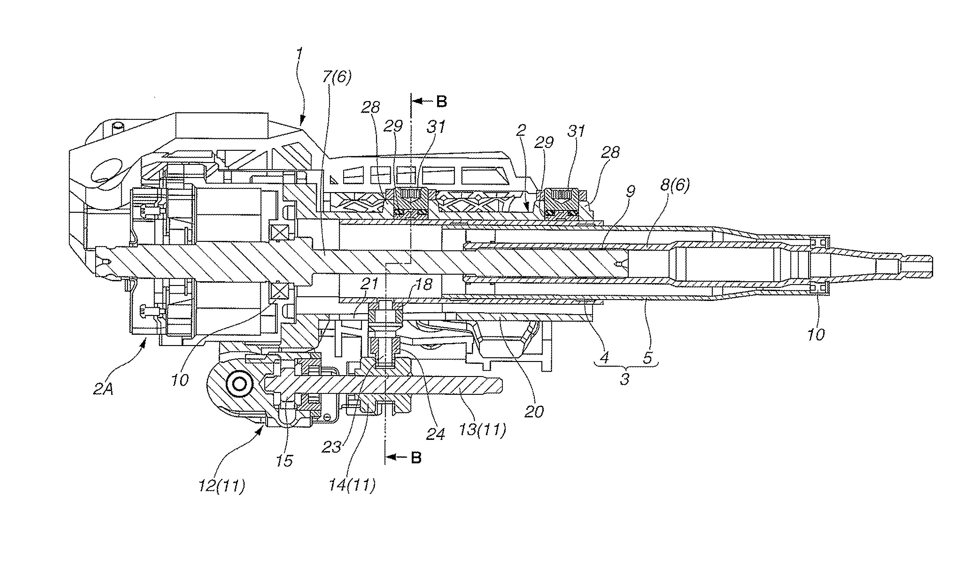
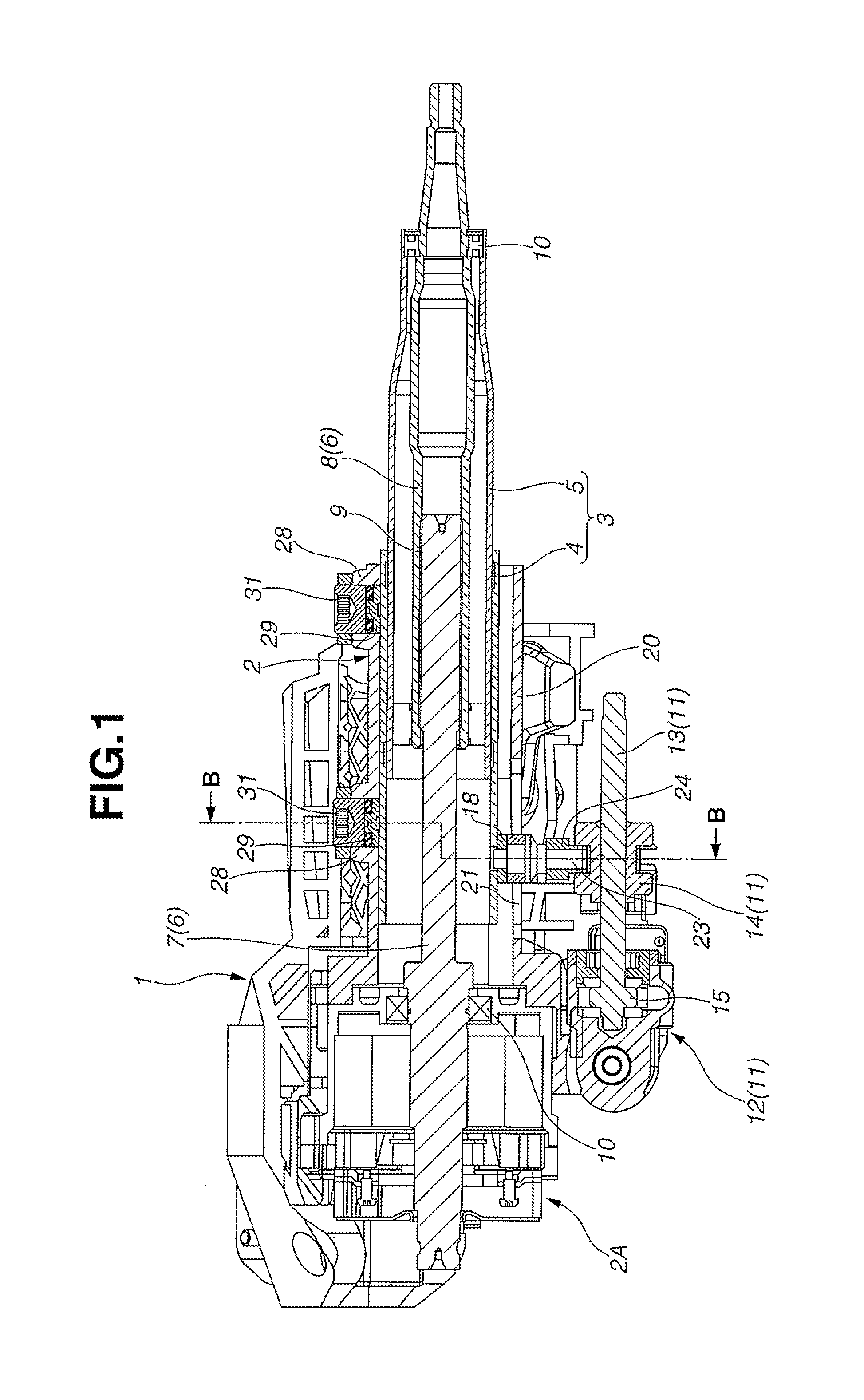
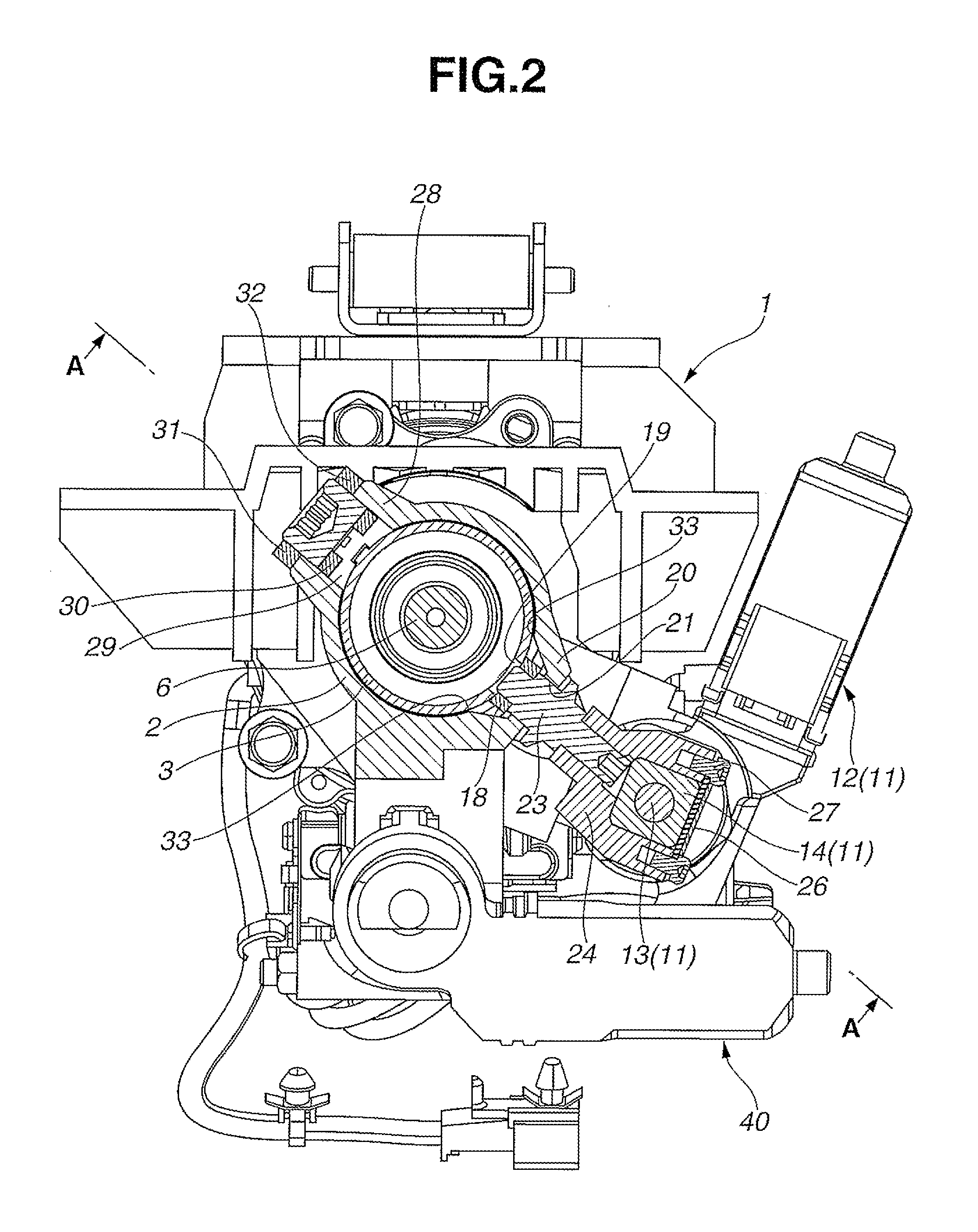
[0017]Referring now to the accompanying drawings, a first embodiment of an electrically-driven steering column apparatus according to the present invention is illustrated. FIG. 1 is a cross-sectional explanatory view taken along the line A-A of FIG. 2, i.e., a longitudinal cross-sectional view taken along the length of the electrically-driven steering column apparatus. FIG. 2 is a cross-sectional explanatory taken along the line B-B of FIG. 1. Moreover, FIG. 3 is an exploded perspective view showing a relationship between a lower jacket 2 and an upper jacket 3 of the electrically-driven steering column apparatus.

[0018]As shown in FIG. 1, the lower jacket 2 is provided to have a generally hollow cylindrical shape and fixedly supported by a highly-rigid mounting bracket 1 which is to be fixed on the side of a vehicle body. The upper jacket 3 having the same shape (a generally hollow cylindrical shape) is inserted into the lower jacket 2 in such a manner as to be slidable in the axial ...


PUM


Abstract

Electrically-driven steering column apparatus including: lower jacket; upper jacket axially slidably inserted thereinto; and telescopic drive disposed astride these two jackets. The telescopic drive contains: support member; screw shaft connected to the support member; and electric motor unit fixed to the lower jacket. The screw shaft is rotatably driven by the motor unit to make slidable motion of the upper jacket with respect to the lower jacket thereby allowing telescopic operation. The lower jacket has axially extending evacuation section shaped by partially increasing the inner diameter of the lower jacket, thereby allowing the passage of nut member provided on the upper jacket. Attaching bolt is screwed into the nut member through longitudinally extending rectangular hole defined by the evacuation section. The support member is supported by the upper jacket through the attaching bolt. Pushing member is disposed circumferentially opposite to the evacuation section, for pushing the upper jacket inwardly.

Description

BACKGROUND OF THE INVENTION[0001]The present invention relates to improvements in an electrically-driven steering column apparatus wherein its telescopic motion for adjusting the position of a steering wheel in an axial direction is adapted to be caused by electric power.[0002]In a steering column apparatus equipped with a telescopic function, an upper jacket is axially movably fitted in a lower jacket supported on a vehicle body side while an electric drive for telescopic motion is disposed astride the lower and upper jackets. For example, the electric drive is comprised primarily of an electric motor unit supported with the lower jacket, a screw shaft that can move the upper jacket forward or backward by the activation of the electric motor unit, and a supporting member connecting one end of the screw shaft to the upper jacket.[0003]With regard to such an electrically-driven steering column apparatus, Japanese Patent Application Publication No. 2001-018809 discloses a technique of...

Claims


Application Information

Patent Timeline
IPC IPC(8): B62D1/181B62D1/185
CPCB62D1/185B62D1/181
Inventor WARASHINA, TOSHIHIKO
Owner FUJI KIKO CO LTD
Why Eureka
Try Eureka