Bidirectional conversion architecture with energy storage

a conversion architecture and energy storage technology, applied in the field of aircraft electrical systems, can solve the problems of increasing the weight and volume of the system, undesirable frequent operation of the clutch, and inefficient discharging of regenerated power into resistors

Active Publication Date: 2016-03-10
HONEYWELL INT INC
View PDF4 Cites 24 Cited by
  • Summary
  • Abstract
  • Description
  • Claims
  • Application Information

AI Technical Summary

Benefits of technology

[0007]In another aspect of the present invention, a battery-based power system for traction motors of an electric taxi system (ETS) of an aircraft may comprise: a battery unit coupled with a DC link; a traction-motor bidirectional DC-AC converter interposed between the DC link and a traction motor of the ETS; and an adaptive power controller configured to control DC power flow from the battery unit

Problems solved by technology

Frequent operation of the clutch is undesirable from a life and reliability perspective.
Dissipating regenerated power in

Method used


Image

  • Bidirectional conversion architecture with energy storage
  • Bidirectional conversion architecture with energy storage
  • Bidirectional conversion architecture with energy storage

Examples


Embodiment Construction

[0018]The following detailed description is of the best currently contemplated modes of carrying out the invention. The description is not to be taken in a limiting sense, but is made merely for the purpose of illustrating the general principles of the invention, since the scope of the invention is best defined by the appended claims.

[0019]Various inventive features are described below that can each be used independently of one another or in combination with other features.

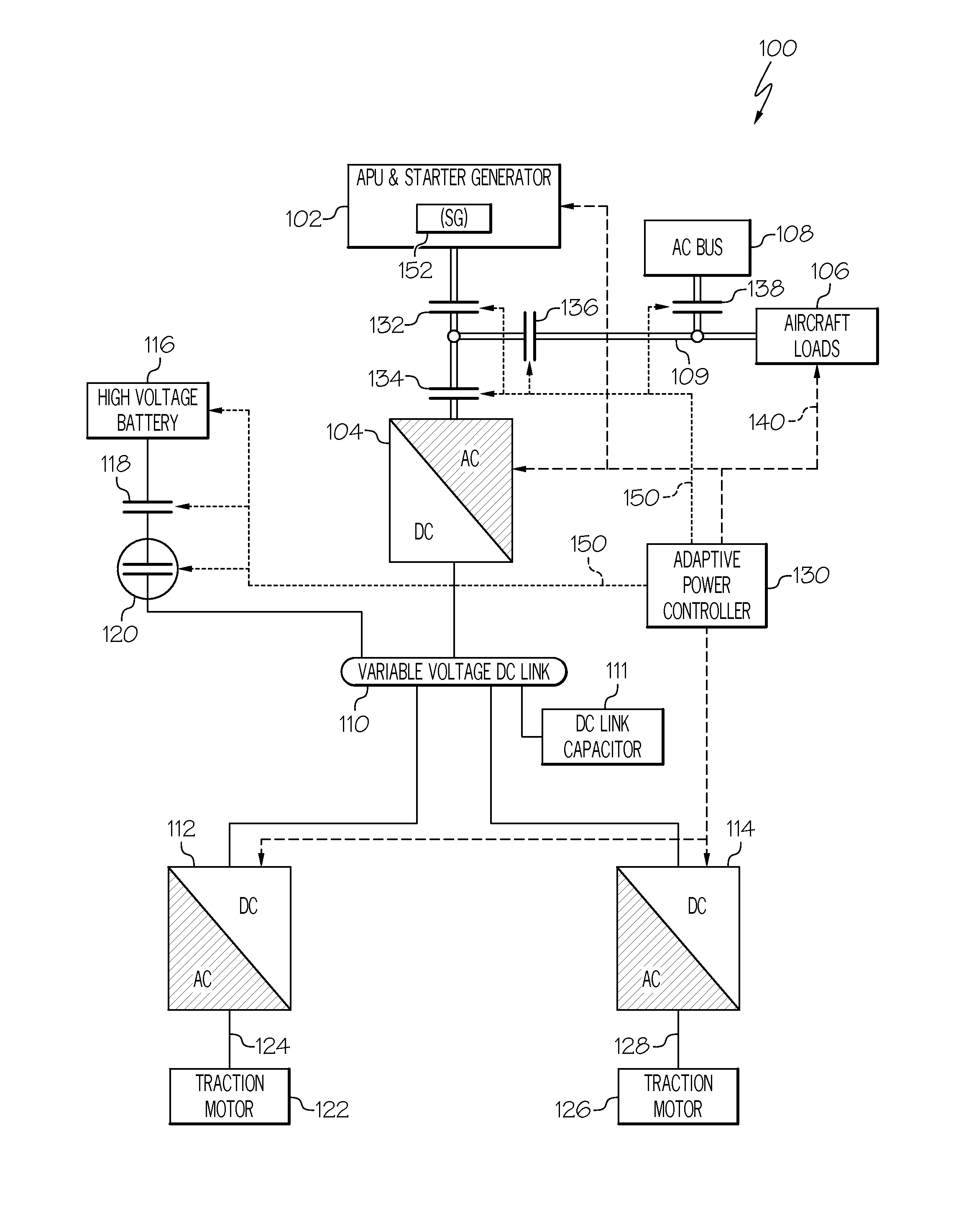
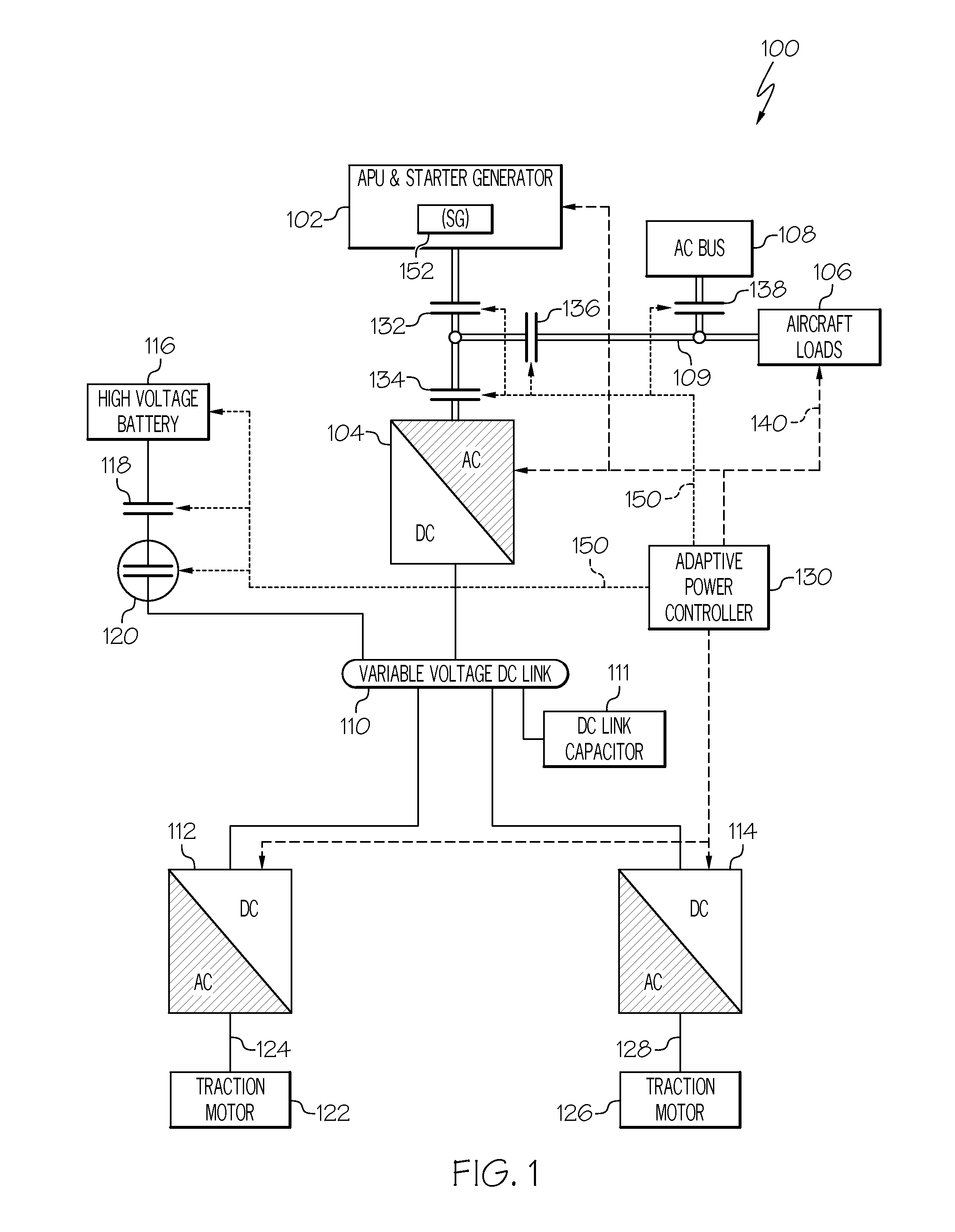
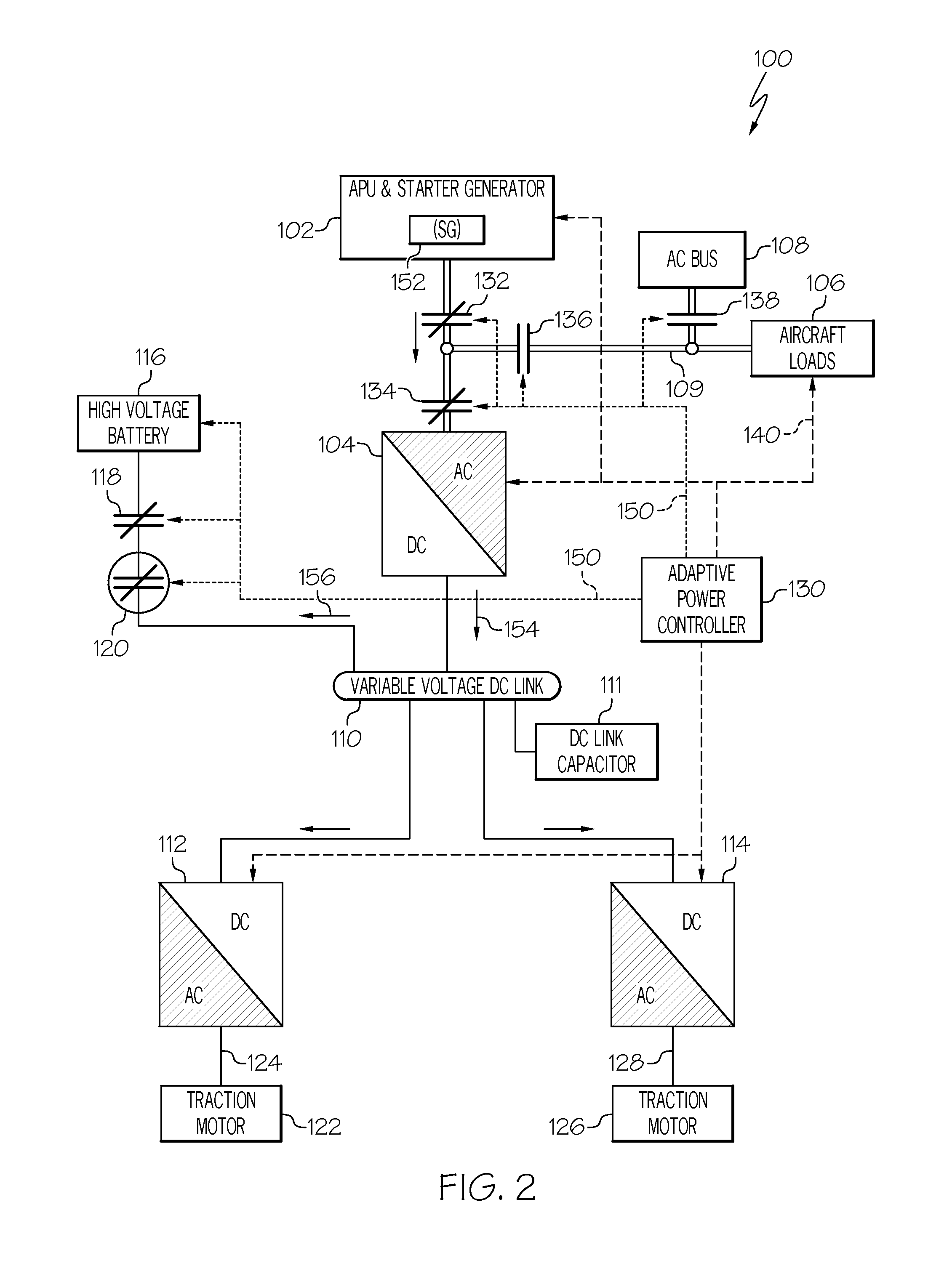
[0020]The present invention generally provides an aircraft electrical system that employs an energy storage device as an adjunct source of electrical power for an electric taxi system (ETS). More particularly, the present invention provides for a system in which energy produced by regenerative braking is effectively utilized to, among other things, power ancillary electrical loads or reduces mechanical loads on the APU.

[0021]Turning now to the description and with reference first to FIG. 1, a schematic diagram may...


PUM


Abstract

An electrical system for an aircraft with an electric taxi system (ETS), the electrical system may include at least one traction motor, a DC link and at least one traction-motor bidirectional DC-AC converter interposed between the at least one traction motor and the DC link. An engine-driven power source may be configured to provide DC power to the DC link or extract DC power from the DC link. A battery unit may be configured to provide DC power to the DC link or extract DC power from the DC link. An adaptive power controller may be interconnected with the power source, the battery unit and the at least one traction-motor bidirectional DC-AC converter and configured to regulate voltage of DC power delivered to the DC link.

Description

BACKGROUND OF THE INVENTION[0001]The present invention relates to aircraft electrical systems and, more particularly, to electrical systems on aircraft that employ electric taxi systems.[0002]In a typical aircraft employing an electric taxi system (ETS), landing gear wheels are driven by electric motors which are provided with electrical power produced by an on-board auxiliary power unit (APU). In order to fully realize the economic benefits of employing an ETS, main engines of an aircraft are not operated during ground-based movement. Consequently the APU is tasked with providing not only electrical power for the ETS motors but also air conditioning power and power for a full array of electrical loads of the aircraft. Thus an aircraft equipped with ETS may need to be fitted with a non-conventional high capacity APU.[0003]Aircraft without ETS are pushed back from a gate with a tug. During tug push-back the tug controls the aircraft movement, including braking, so the crew do not use...

Claims


Application Information

Patent Timeline
IPC IPC(8): G05D1/02H02J4/00H02J7/00
CPCG05D1/0202H02J7/0055H02J2007/0059H02J4/00H02J7/0065H02J7/14H02J7/345B60L7/10H02J1/08H02J1/12B60L2200/10B60L2210/10B60L2220/42B60L2240/547B60L58/13B60L58/20B60L7/16H02J2207/40H02J2207/20H02J2310/44Y02T10/64Y02T10/70Y02T10/72B64C25/42B64C25/405B64D2221/00H02P3/14Y02T50/80
Inventor DIVITO, ROCCOKOJORI, HASSAN ALIMORCOV, NICOLAEPEARSON, WAYNEANGHEL, CRISTIAN
Owner HONEYWELL INT INC
Why Eureka
Try Eureka