Fault detection and isolation using a common reference clock

a common reference clock and fault detection technology, applied in the field of electric power systems, can solve the problems of low-current faults, ineffective detection of high-impedance, low-current faults, etc., and achieve the effect of only detecting high-current fault events and reporting them with conventional fci technologies

Inactive Publication Date: 2016-03-10
SOUTHERN STATES
View PDF12 Cites 28 Cited by
  • Summary
  • Abstract
  • Description
  • Claims
  • Application Information

AI Technical Summary

Benefits of technology

[0011]The present invention meets the needs described above through a fault detection and isolation system for distribution electric power lines utilizing a remote reference voltage signal, multiple three-phase current monitors producing asynchronous event data, and a common reference clock. A voltage measurement obtained for a power line at a substation may be synchronized with multiple current phase measurements taken at a power monitoring location along that particular power line. The same voltage measurement may be similarly synchronized with current measurements taken at multiple current monitoring locations along the power line. As a result, the same voltage measurement may be synchronized with current measurements taken multiple tap points along the power allowing a fault on a tapped line segment to be identified, located and isolated. An alternative embodiment utilizes differential current analysis utilizing current measurements from adjacent current monitoring locations correlated to a common reference clock to locate faults and therefore does not require a voltage measurement.

Problems solved by technology

This works well for many faults because many distribution circuit faults cause currents well in excess of the normal load current.
Although conventional FCI are effective at detecting low-impedance, high-current faults, they are not effective for detecting high-impedance, low-current faults even when they send their information to a common monitoring point.
As a result, conventional FCI technologies only detect and report high-current fault events.
In addition, there are conventional overcurrent devices with the ability to determine the location of faults on radial lines, but they only trigger for high-current faults.
As a result, virtually all of the current technologies utilized on power lines for detecting and locating low-impedance, high-current faults are ineffective for detecting high-impedance, low-current faults.
But even with three-phase synchronized information available, conventional technology is not capable of determining the location of the fault or isolating the specific line segment where the fault has occurred on power lines with multiple tap points.
Moreover, existing fault monitoring techniques located between the substations are not able to detect the presence of high-impedance faults, which limits high-impedance fault location detection to devices located in substations.
Current FCI technology used for overcurrent protection is typically not capable of providing any indication of the presence these high-impedance faults.
When high-impedance faults occur, which in about 70% of faults, they present significant safety concerns to the public because they are often caused by energized lines touching trees or broken, still energized lines touching the ground creating significant electrical hazards.
Since high-impedance faults are not detectable by conventional overcurrent FCI sensors, their location can be nearly impossible to find.
Single-phase current monitors are not capable of determining the location of these dangerous high-impedance faults.
While some currently available techniques have been used to detect the presence of high-impedance faults by detecting a harmonic signature characteristic of a fault caused by “arcing” in the faults, these techniques do not determine the location or direction to the fault.
In addition, visual inspection also has limits because things like cracks in insulators can be difficult to find visually, for example when a crack is on the other side of the insulator from the line of sight.
The result is that a distribution circuit can experience a high-impedance fault and the utility crew may not be able to even detect the presence of the fault because the overcurrent detectors typically installed on distribution lines do not respond to the current levels created by the high-impedance fault.
Even when more sophisticated (and expensive) equipment is installed to detect the presence of high-impedance faults, the location or the direction to the fault from the monitoring equipment cannot be detected.
With currently available technology, detecting the location or the direction to the fault from the monitoring equipment presently requires even more expensive solutions.

Method used


Image

  • Fault detection and isolation using a common reference clock
  • Fault detection and isolation using a common reference clock
  • Fault detection and isolation using a common reference clock

Examples


Embodiment Construction

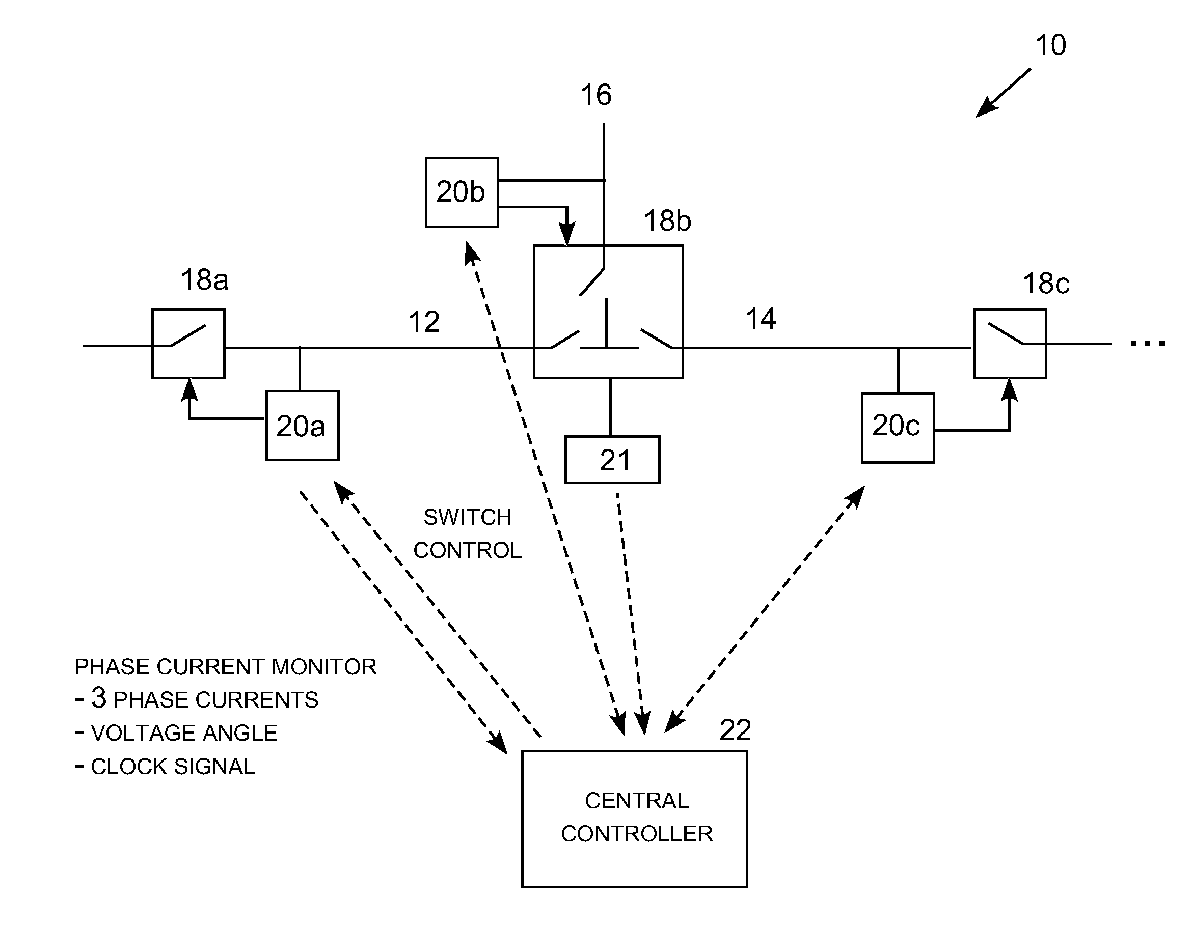
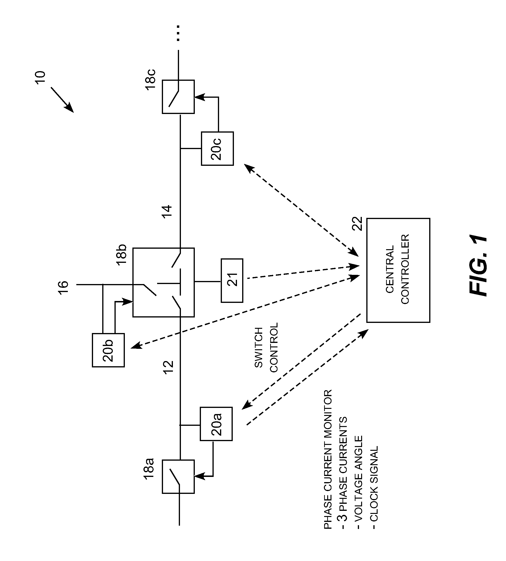
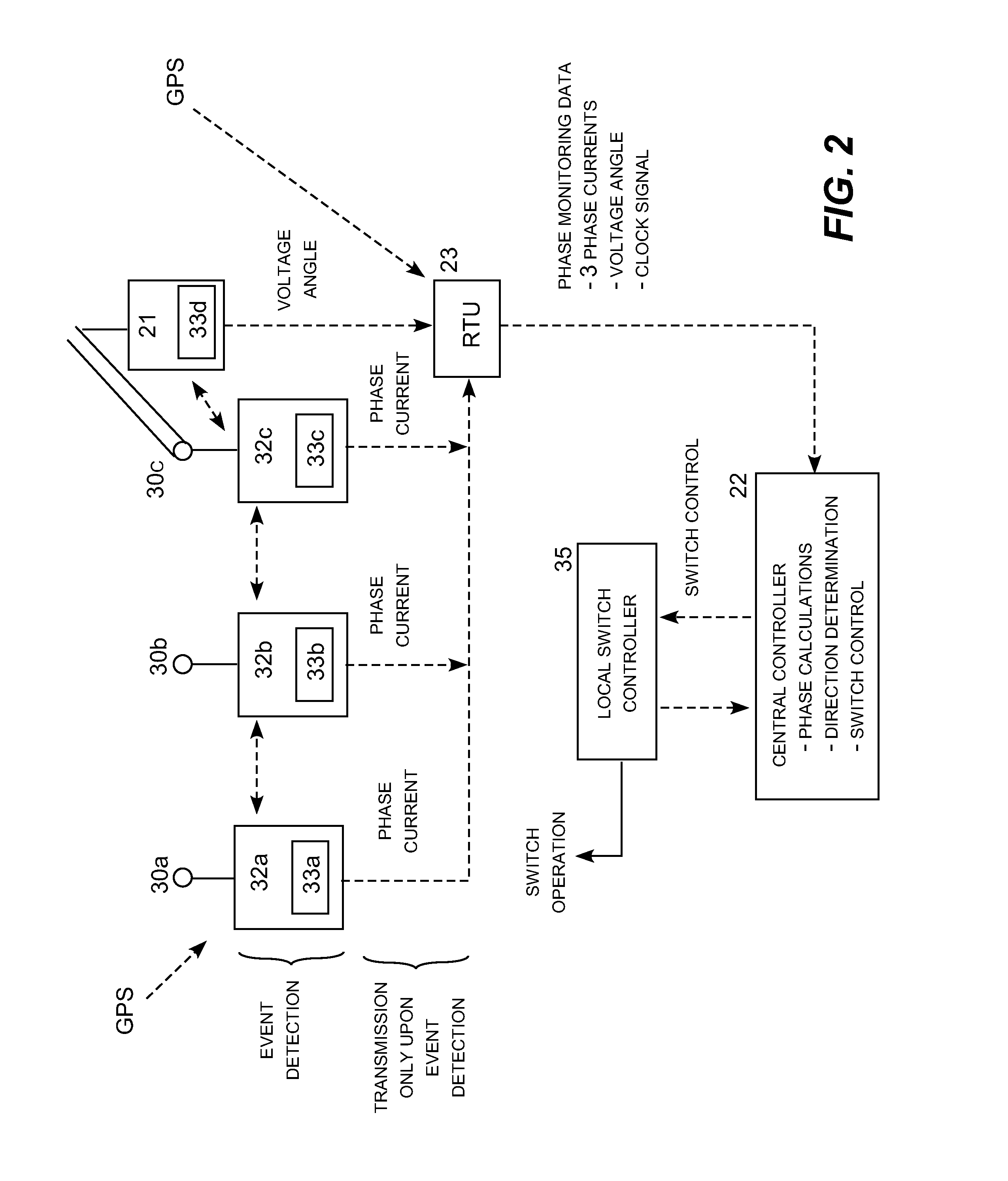
[0025]The present invention may be embodied in a fault detection and isolation system for distribution electric power lines utilizing a remote reference voltage signal, multiple three-phase current monitors producing asynchronous event data, and a common reference clock. Specific techniques for detecting the presence of high-impedance faults using simultaneous three-phase current monitors are described in U.S. Pat. No. 8,717,721; specific techniques for determining the direction to the fault from the sequenced currents are described in U.S. patent application Ser. No. 13 / 229,808; and specific techniques for sectionalizing the distribution network to isolate detected faults are described in U.S. Pat. No. 8,659,862, which are incorporated by reference. U.S. patent application Ser. No. 13 / 864,611, which is also incorporated by reference, describes a high-impedance fault detection system utilizing local current monitors and a local voltage angle detector.

[0026]While the techniques descr...


PUM


Abstract

A fault detection and isolation system for distribution electric power lines utilizing a remote reference voltage signal, multiple three-phase current monitors producing asynchronous event data, and a common reference clock. A voltage measurement obtained for a power line at a substation may be synchronized with multiple current phase measurements taken at a power monitoring location along that particular power line. The same voltage measurement may be similarly synchronized with current measurements taken at multiple current monitoring locations along the power line. As a result, the same voltage measurement may be synchronized with current measurements taken multiple tap points along the power allowing a fault on a tapped line segment to be identified, located and isolated. An alternative embodiment utilizes differential current analysis utilizing current measurements from adjacent current monitoring locations correlated to a common reference clock to locate faults and therefore does not require a voltage measurement.

Description

REFERENCE TO RELATED APPLICATIONS[0001]This application incorporates by reference U.S. patent application Ser. No. 12 / 864,611 (Pub. No. 2013-0229735) entitled “High-Impedance Fault Detection and Isolation System” filed Apr. 17, 2013; Ser. No. 13 / 229,808 (Pub. No. 2012-0062239) entitled “Directional Fault Sectionalizing System” filed Sep. 12, 2011; and U.S. Provisional Patent Application Ser. No. 61 / 381,518 entitled “Fault Location Detection on Tapped Transmission Lines,” filed Sep. 10, 2010. Commonly owned U.S. Pat. Nos. 7,191,074; 7,683,798; 8,392,130; and 8,659,862 are also incorporated by reference.TECHNICAL FIELD[0002]The present invention is directed to electric power systems and, more particularly, to an electric power line fault detection and isolation system utilizing multiple three-phase current monitors producing asynchronous event data correlated to a common reference clock.BACKGROUND[0003]Line mounted fault detectors (also known as faulted circuit indicators or FCI's) ar...

Claims


Application Information

Patent Timeline
Patent Type & Authority Applications(United States)
IPC IPC(8): H02H1/00G05B15/02H02H3/08H02H3/10H02H7/22H02H7/26
CPCH02H1/0092H02H7/226H02H3/083G05B15/02H02H3/10H02H7/262H02H1/003H02H3/081
Inventor ROSTRON, JOSEPH R.JIYUAN, FAN
Owner SOUTHERN STATES
Why Eureka
Try Eureka