Power conversion system and connector

a power conversion system and connector technology, applied in secondary cell servicing/maintenance, emergency power supply arrangements, batteries, etc., can solve the problems of not having a function of the charger/discharger disclosed in document 1 and not being able to immediately take countermeasures

Active Publication Date: 2016-03-10
PANASONIC INTELLECTUAL PROPERTY MANAGEMENT CO LTD
View PDF12 Cites 27 Cited by
  • Summary
  • Abstract
  • Description
  • Claims
  • Application Information

AI Technical Summary

Benefits of technology

[0010]According to the configuration of the power conversion system of the present invention, it is possible to obtain an advantage that a malfunction in a period in which transmission of electric power between a connector and a battery is stopped can be detected.
[0011]According to the configuration of the connector of the present invention, it is possible to obtain an advantage that the connector is inhibited from being removed from an apparatus when a malfunction is detected by a processing module.

Problems solved by technology

However, the charger / discharger disclosed in Document 1 does not have a function of detecting the presence or absence of a malfunction in the electromagnet switching device provided in the charge / discharge connector.
Thus, it is not possible to immediately take countermeasures such as sending an alarm notification or the like to users even when a malfunction such as weld of the electromagnet switching device in the charge / discharge connector occurs.

Method used


Image

  • Power conversion system and connector
  • Power conversion system and connector
  • Power conversion system and connector

Examples


embodiment 1

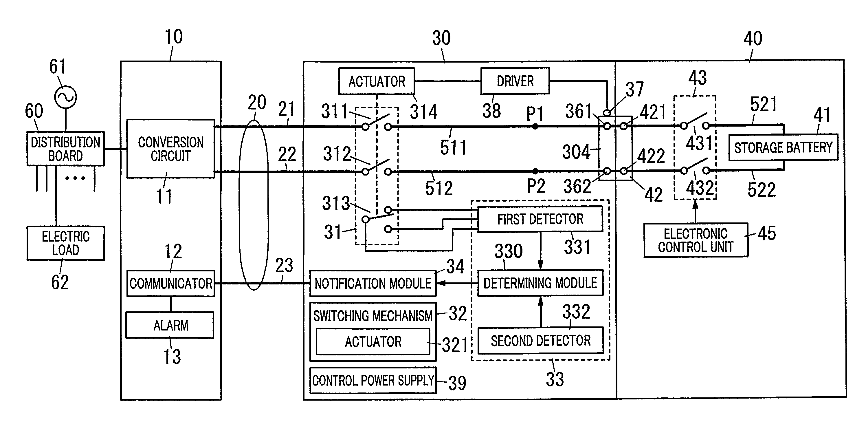
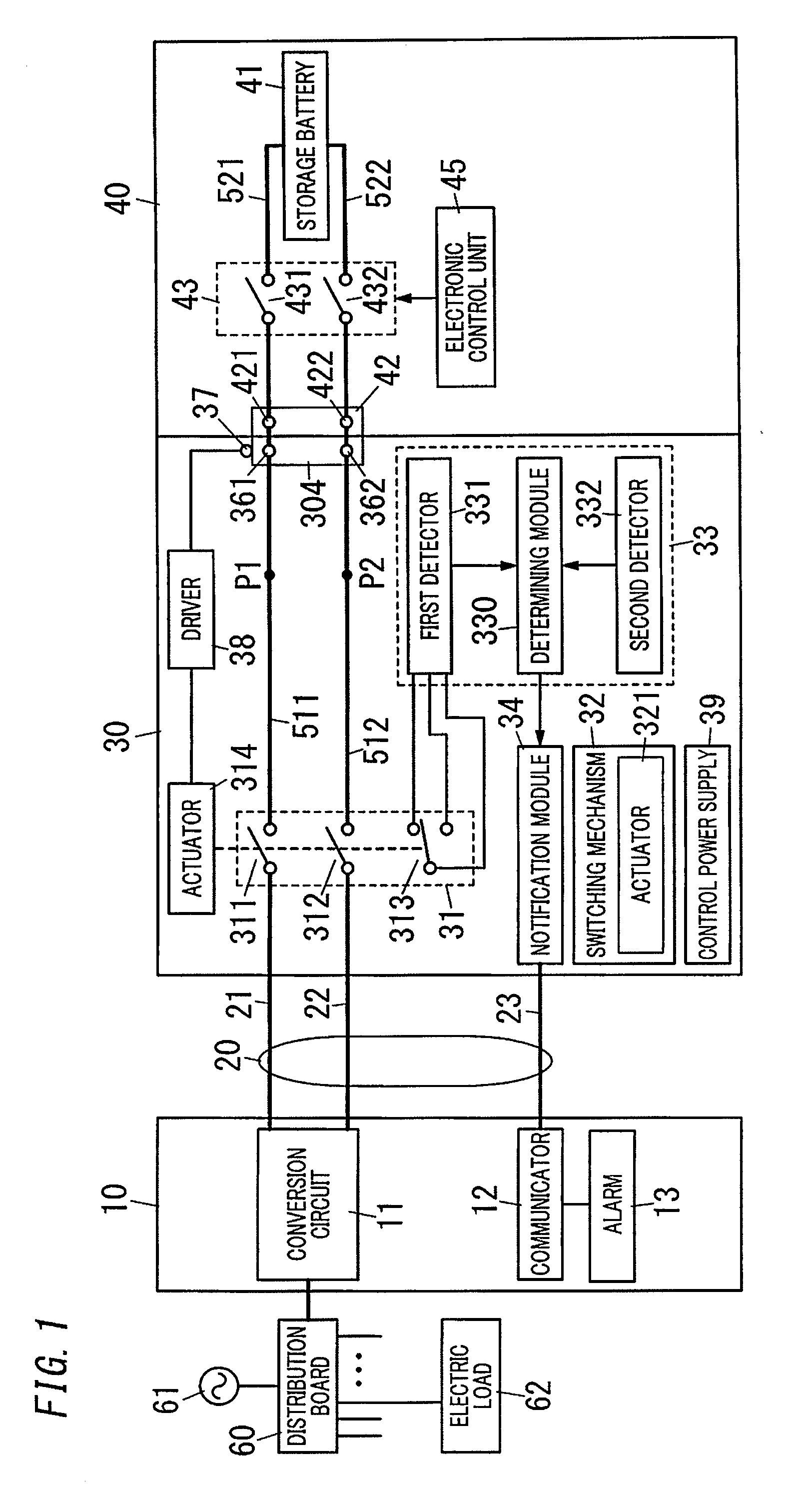
[0037]As illustrated in FIG. 1, a power conversion system described below includes a power conversion device 10 and a connector 30. The power conversion device 10 includes a conversion circuit 11 configured to convert AC and DC electric power bidirectionally. A housing of the power conversion device 10 may be a wall-mounted housing attached to a wall of a house or a stationary housing installed on a ground surface. The conversion circuit 11 is configured to be electrically connected to a distribution board 60 provided in the house and connected to the connector 30 with a cable 20. The distribution board 60 allows a main circuit connected to a system power supply 61 to branch into a plurality of systems of branch circuits. An electric load 62 is electrically connected to the branch circuit.

[0038]The conversion circuit 11 has a function of converting AC electric power supplied from the distribution board 60 into DC electric power having a voltage value suitable for a storage battery 4...

embodiment 2

[0114]In Embodiment 1, a first detector 331 uses an auxiliary contact 313 provided in a switching device 31 separately from contacts 311 and 312 which are main contacts in order to detect an open state and a closed state of the switching device 31. In contrast, in the present embodiment, a configuration example in which the first detector 331 detects the open state and the closed state of the switching device 31 without the auxiliary contact 313. Hereinafter, the same constituent elements as those of Embodiment 1 will be denoted by the same reference numerals, and the description thereof will not be provided.

[0115]In the present embodiment, the first detector 331 identifies the open state and the closed state of the switching device 31 by monitoring a voltage value between measurement points P1 and P2 set in electric paths 511 and 512 of a connector 30 and comparing the voltage value with a predetermined threshold. As illustrated in FIG. 1, the measurement points P1 and P2 are set i...

embodiment 3

[0124]In the configuration of the present embodiment illustrated in FIG. 4, a processing module 33 provided in a connector 30 is configured to detect a malfunction in a switching device 43 provided in an electric vehicle 40 rather than detecting only a malfunction in a switching device 31 included in the connector 30. The processing module 33 is configured to monitor a voltage value between measurement points P1 and P2 set in two electric paths 511 and 512 between the switching device 31 and an insertion portion 304 and detect a malfunction in the switching devices 31 and 43 based on the voltage value.

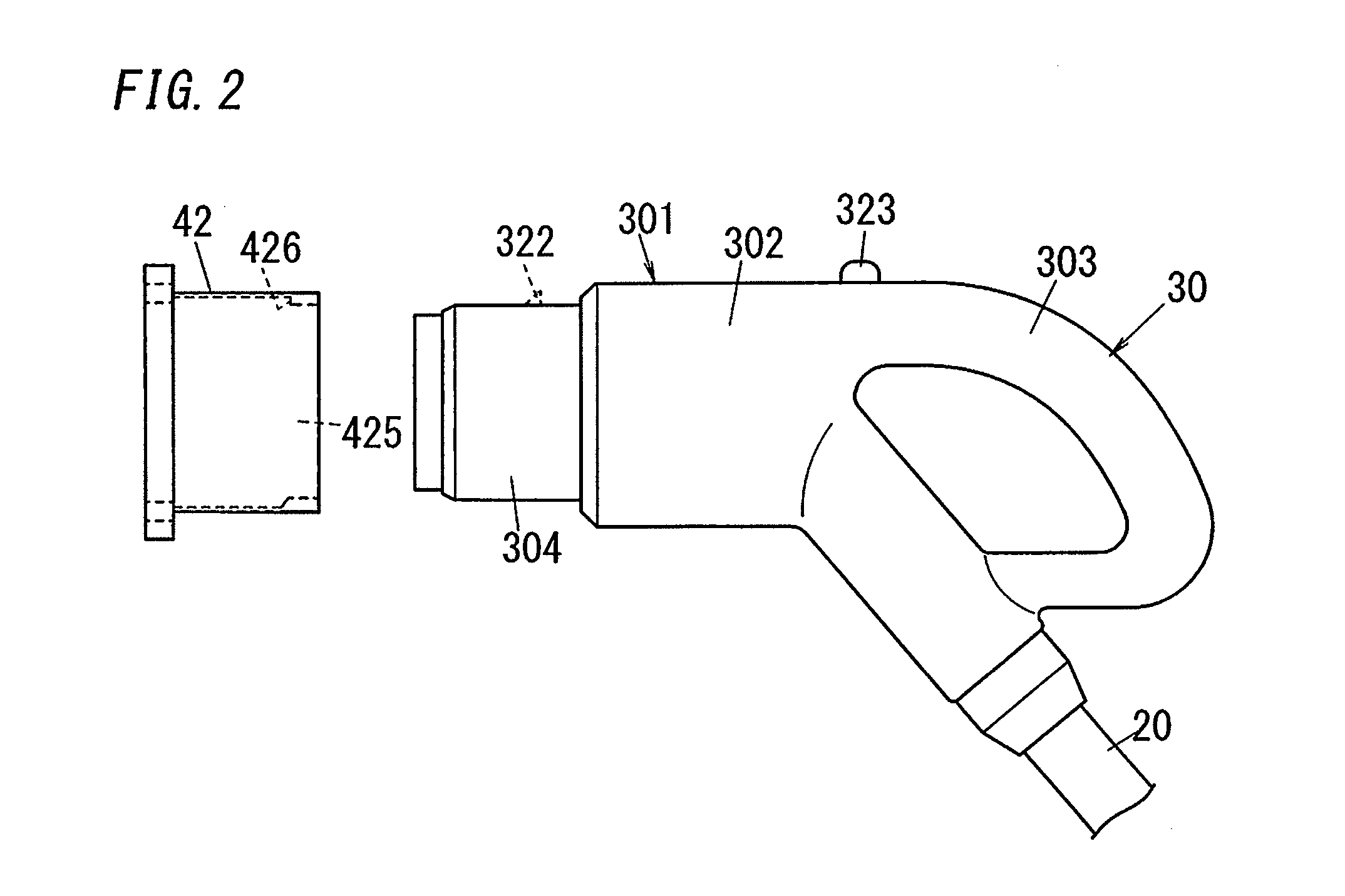
[0125]In Embodiment 2, the voltage value between the measurement points P1 and P2 is measured in a state in which a small current flows into the electric paths 511 and 512 at a time point at which the state of the body 301 of the connector 30 changes from the attached state to the unattached state. In contrast, the processing module 33 of the present embodiment is configured to detect ...


PUM


Abstract

A power conversion system includes a power conversion device, a connector, and a processing module. The power conversion device is connected to a power system. The attached state and the unattached state of the connector relative to a connecting port that is provided in an apparatus having a battery mounted therein can be selected. The processing module is configured to determine that a malfunction has occurred when a voltage is applied to a portion that electrically connects the connector and the connecting port in a period in which transmission of electric power with respect to the battery is stopped.

Description

TECHNICAL FIELD[0001]The present invention generally relates to a power conversion system and a connector, and more particularly, to a power conversion system that enables electric power of a battery mounted in an apparatus to be supplied to a power system and a connector configured to be connected to the apparatus.BACKGROUND ART[0002]In recent years, from the consideration of limited resources and environmental issues, electric vehicles in which a storage battery is mounted as a travelling energy source are gathering attention. Moreover, a charger / discharger including a main body, a cable, and a charge / discharge connector in order to charge or discharge a storage battery mounted in an electric vehicle has been proposed (for example, Document 1 (JP Pub. No. 2013-31348)).[0003]In the main body of the charger / discharger disclosed in Document 1, an electromagnet switching device that interrupts current flowing in the cable when the value of the current is a predetermined value or highe...

Claims


Application Information

Patent Timeline
Patent Type & Authority Applications(United States)
IPC IPC(8): H02J9/06B60L11/18
CPCB60L11/1851H02J9/061H01M10/44H01M2220/20Y02T90/14B60L3/00B60L3/04B60L2250/10B60L2250/16B60L2250/24B60L2270/30Y04S10/126B60L53/16B60L53/30B60L55/00B60L53/11B60L58/20B60L58/24B60L58/19B60L58/12B60L53/62Y02E60/00Y02T10/70Y02T10/7072Y02T90/12Y02E60/10
Inventor TAMURA, HIDEKIKAGAWA, TAKUYAKIDERA, KAZUNORI
Owner PANASONIC INTELLECTUAL PROPERTY MANAGEMENT CO LTD
Why Eureka
Try Eureka