

Power generator
a power generator and diametrical size technology, applied in the field of power generators, can solve the problems of large diametrical size of each coil, difficult to cause uniform stress, and inability to increase the variation of magnetic flux density, etc., to achieve the effect of improving the power generating efficiency of the power generator, large diametrical size of the coil, and sufficient spa
- Summary
- Abstract
- Description
- Claims
- Application Information
AI Technical Summary
Benefits of technology
Problems solved by technology
Method used
Image

Examples
first embodiment
[0076]First, description will be given to a power generator according to a first embodiment of the present invention.
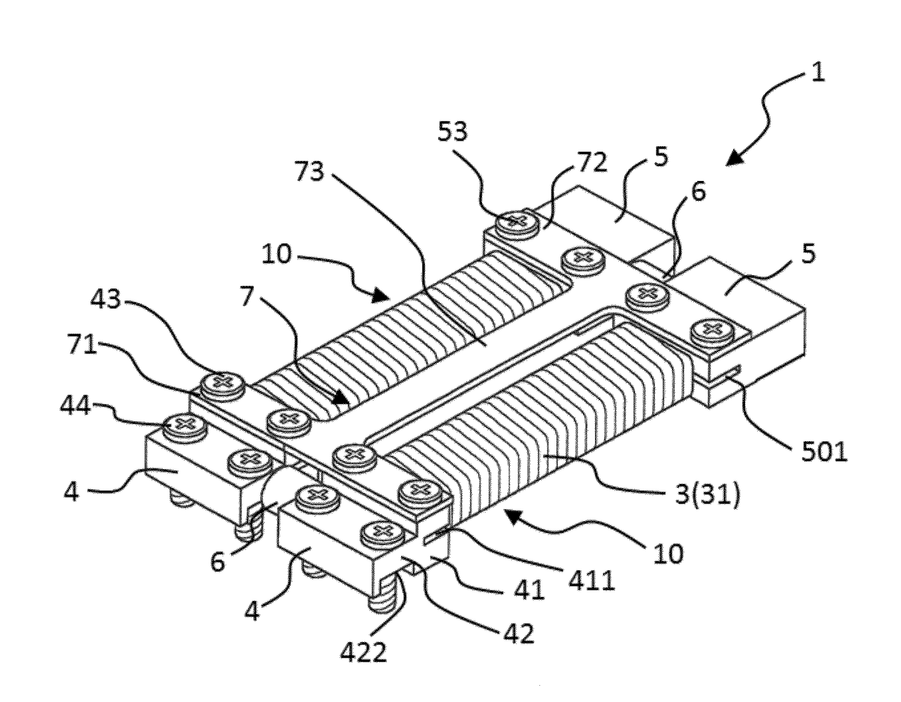
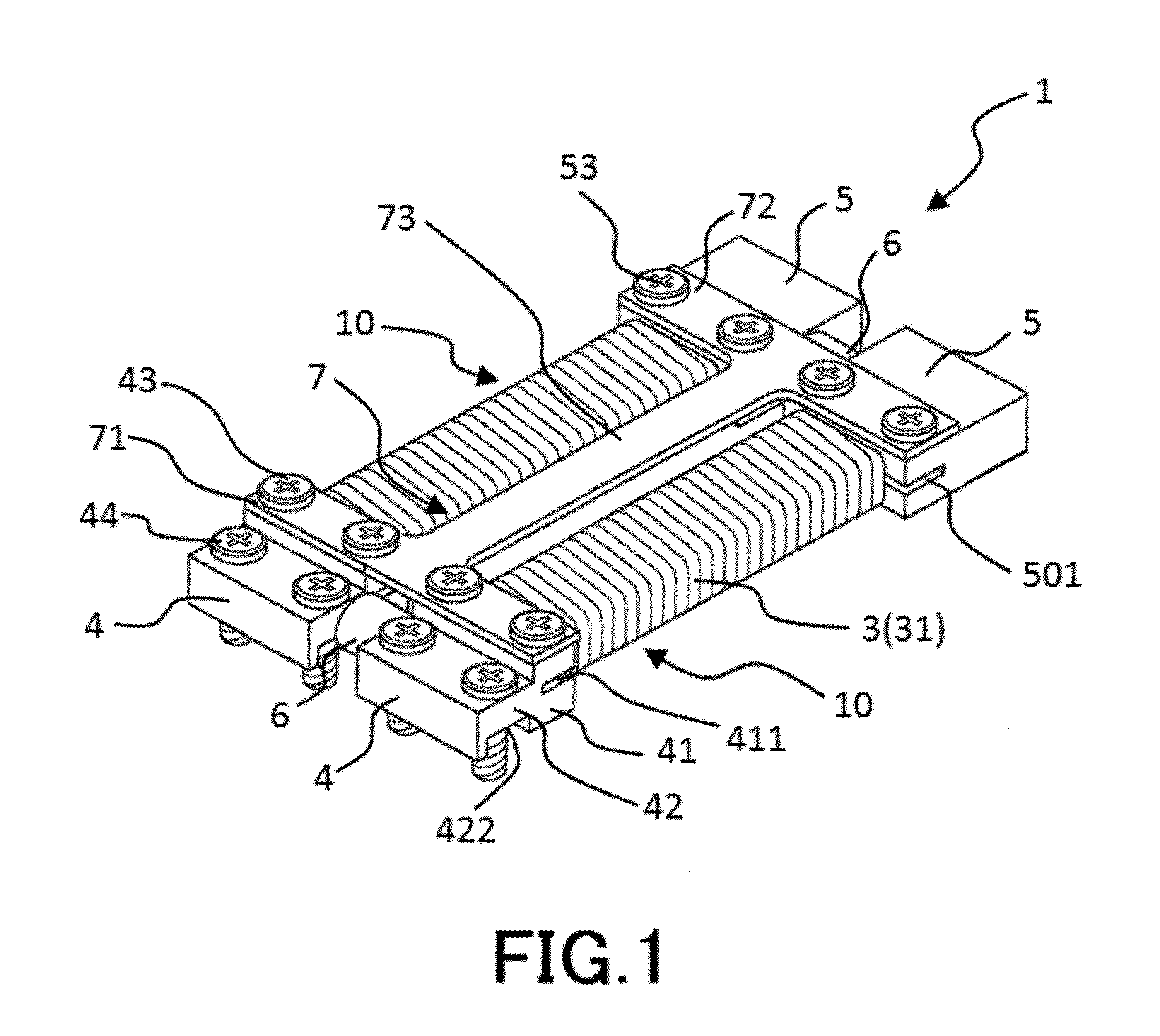
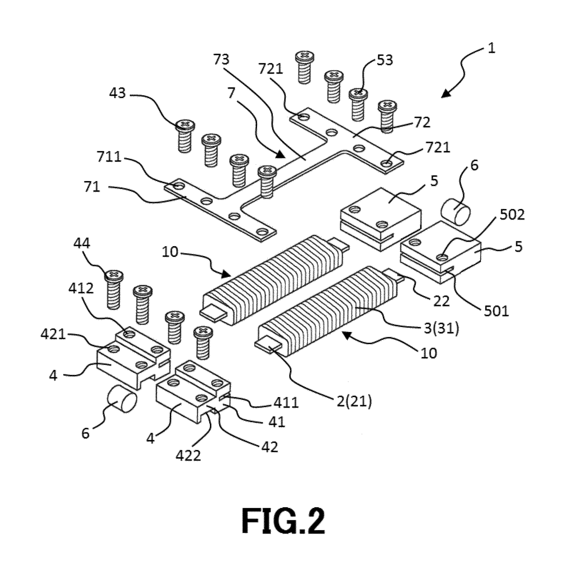
[0077]FIG. 1 is a perspective view showing a power generator according to a first embodiment of the present invention. FIG. 2 is an exploded perspective view showing the power generator shown in FIG. 1. FIG. 3(a) is a side view showing the power generator shown in FIG. 1. FIG. 3(b) is a side view showing the power generator shown in FIG. 3(a) from which a coil is removed from each magnetostrictive rod. FIG. 4 is a planar view showing the power generator shown in FIG. 1. FIG. 5 is a front view showing the power generator shown in FIG. 1. FIG. 6 is a side view for explaining a state in which the power generator shown in FIG. 1 is fixedly attached to a vibrating body.
[0078]Hereinafter, an upper side in each of FIGS. 1, 2, 3(a), 3(b), 5 and 6 and a front side of the paper in FIG. 4 are referred to as “upper” or “upper side” and a lower side in each of FIGS. 1, 2, 3(a), 3(...
second embodiment
[0170]Next, description will be given to a power generator according to a second embodiment of the present invention.
[0171]FIG. 12 is a perspective view showing a power generator according to a second embodiment of the present invention. FIG. 13(a) is a side view showing the power generator shown in FIG. 12. FIG. 13(b) is a side view showing the power generator shown in FIG. 13(a) from which the coil is removed from each magnetostrictive rod. FIG. 14(a) is an analysis diagram illustrating an analysis result of stress caused in the magnetostrictive rod and the beam portion of the power generator shown in FIG. 1. FIG. 14(b) is an analysis diagram illustrating an analysis result of stress caused in the magnetostrictive rod and the beam portion of the power generator shown in FIG. 12.
[0172]Hereinafter, an upper side in each of FIGS. 12, 13(a), (b) and 14(a), (b) is referred to as “upper” or “upper side” and a lower side in each of FIGS. 12, 13(a), (b) and 14(a), (b) is referred to as “l...
third embodiment
[0191]Next, description will be given to a power generator according to a third embodiment.
[0192]FIG. 15 is a perspective view showing a power generator according to a third embodiment of the present invention. FIG. 16 is an exploded perspective view showing the power generator shown in FIG. 15. FIG. 17(a) is a side view showing the power generator shown in FIG. 15. FIG. 17(b) is a side view showing the power generator shown in FIG. 17(a) from which the coil is removed from each magnetostrictive rod. FIG. 18 is a front view showing the power generator shown in FIG. 15. FIG. 19(a) is a right side view showing a state in which the power generator (the coil is omitted) shown in FIG. 15 is fixedly attached to a vibrating body. FIG. 19(b) is a right side view showing a state in which external force is applied to a distal end of the power generator shown in FIG. 19(a) in a downward direction thereof. FIG. 20 is an analysis diagram illustrating an analysis result of stress caused in the ma...
PUM
| Property | Measurement | Unit |
|---|---|---|
| Young's modulus | aaaaa | aaaaa |
| Young's modulus | aaaaa | aaaaa |
| Young's modulus | aaaaa | aaaaa |
Abstract
Description
Claims
Application Information