Magnetic Induction Antenna for Use in a Wearable Device

a technology of electromagnetic field and wearable devices, applied in the field of wearable devices, can solve the problems of affecting the use of nfmi introduces additional problems, and the use of bluetooth wireless transceivers, so as to improve the placement of the antenna, improve the electromagnetic field orientation, and improve the effect of wearability

Active Publication Date: 2016-03-10
BRAGI
View PDF8 Cites 126 Cited by
  • Summary
  • Abstract
  • Description
  • Claims
  • Application Information

AI Technical Summary

Benefits of technology

[0006]It is a further object, feature, or advantage of the present invention to provide for an improved wearable device.
[0007]It is a still further object, feature, or advantage of the present invention to provide an antenna for NFMI suitable for use in a wearable device to allow for communication with other wearable devices.
[0008]Another object, feature, or advantage of the present invention is to provide an antenna for induction which avoids magnetic fields induced by the printed circuit board and other electronic components associated with a wearable device.
[0009]Yet another object, feature, or advantage of the present invention is to provide for improved placement of an antenna within a wearable device for improved orientation of the electromagnetic field.
[0010]A further object, feature, or advantage of the present invention is to provide for an antenna that is sufficiently powerful for expected tasks and is straightforward in its manufacturing and assembly.
[0011]A still further object, feature or advantage of the present invention is position an antenna relative to a Bluetooth antenna to facilitate enhancement of Bluetooth reception by the Bluetooth antenna.

Problems solved by technology

However, there can be numerous issues when used in particular environments and / or applications.
For example, in the case of wearable devices where a left earpiece is to communicate with a right earpiece there may be issues using Bluetooth wireless transceivers due to a combination of factors involving attenuation, reliability in varied environments and sensitivity.
However, use of NFMI introduces additional problems.
For example, the placement of the antenna may be problematic.
Magnetic fields induced by the PCB limits the areas of the wearable device capable of providing optimal electromagnetic field generation.
In addition, there are concerns regarding the possibility of additional interference generated from other related electronic components.

Method used


Image

  • Magnetic Induction Antenna for Use in a Wearable Device
  • Magnetic Induction Antenna for Use in a Wearable Device
  • Magnetic Induction Antenna for Use in a Wearable Device

Examples


Embodiment Construction

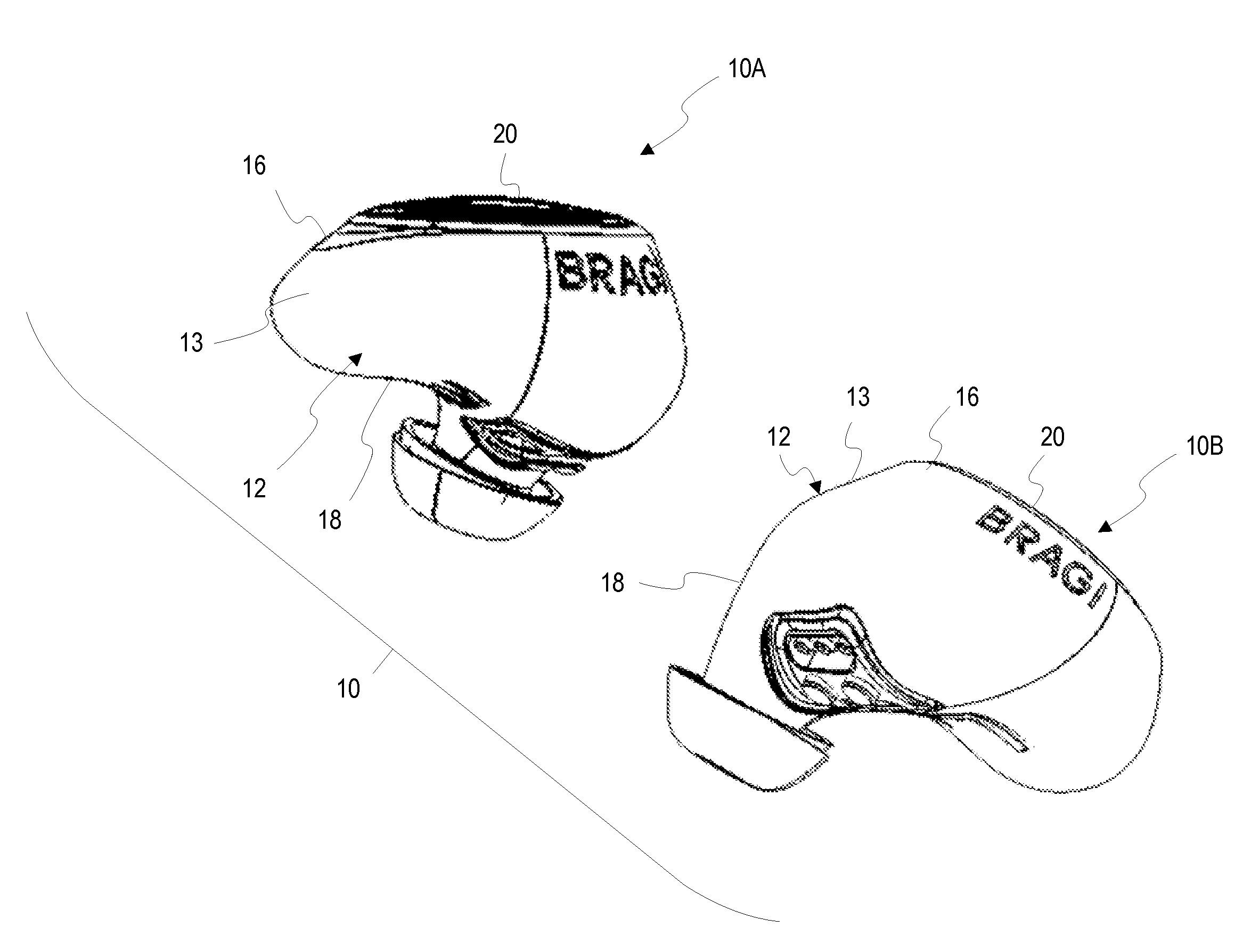
[0027]The present invention relates to an antenna for use in a wearable device. Although generally described herein with respect to a near field magnetic induction (NFMI) antenna for use in an ear piece within a set of ear pieces, it is to be understood that the present invention is not limited to that specific application and may be used as an antenna for induction in other types of devices including other types of wearable devices.

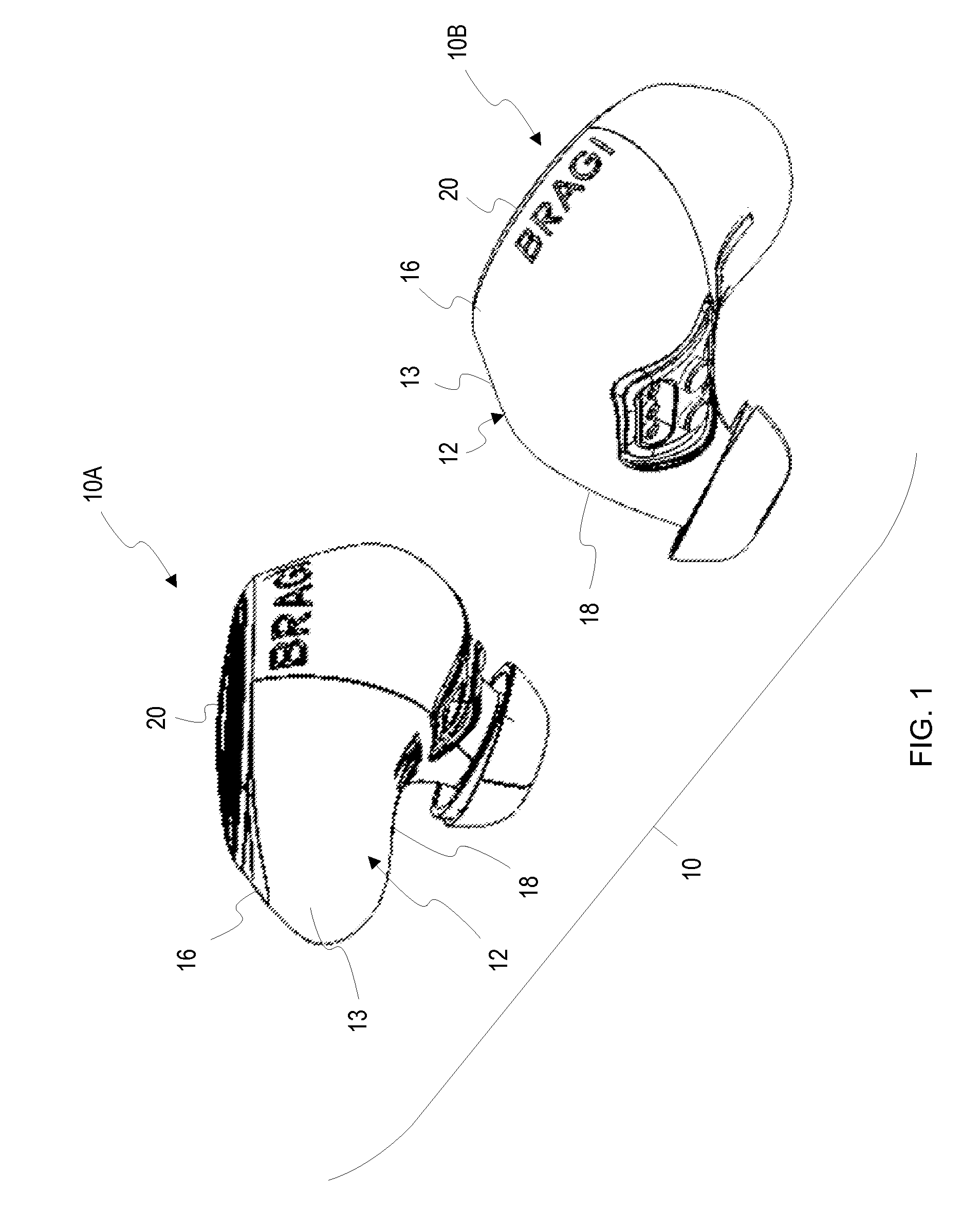
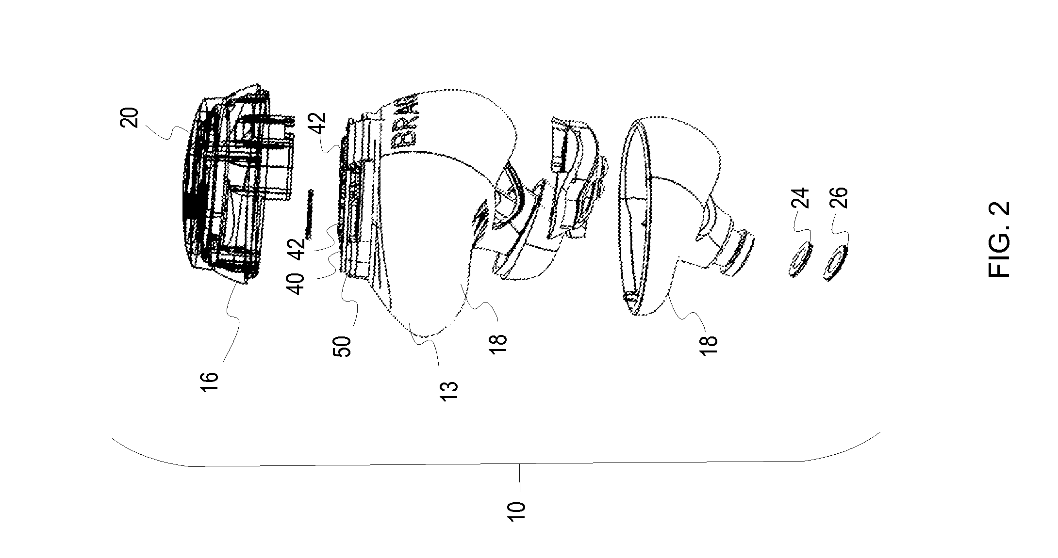
[0028]FIG. 1 illustrates one example of a system 10 which includes a first wearable device 10A in the form of an ear piece and a second wearable device 10B also in the form of an ear piece, each having an ear piece housing 12 with a central portion 13 with an upper portion 16 and a lower portion 18. A light guide assembly 20 is shown operatively connected to the housing to provide for selective illumination to provide feedback to a user. FIG. 2 provides an exploded view of the wearable device 10A. A waterproof pad 24 and protection mesh 26 are shown. In ...


PUM


Abstract

A wearable device includes a housing, a first short range transceiver for far field communication disposed within the housing, a second short range transceiver for near field communication disposed within the housing, wherein the second short range transceiver for near field communications comprises a core and a plurality of coil turns wrapped around the core. The wearable device further includes a generally planar printed circuit board disposed within the housing and having a plurality of components mounted thereto. The core is mounted perpendicularly to the plurality of components mounted on the generally planar printed circuit board to thereby reduce electromagnetic interference. The wearable device may be an earpiece. The core may be mounted at a posterosuperior portion of the wearable device.

Description

[0001]PRIORITY STATEMENT[0002]This application claims priority to U.S. Provisional Patent Application No. 62 / 211,725, filed Aug. 29, 2015, hereby incorporated by reference in its entirety.FIELD OF THE INVENTION[0003]The present invention relates to antenna. More particularly, but not exclusively, the present invention relates to an antenna for use in a wearable device such as an ear piece.BACKGROUND OF THE ART[0004]Various types of wireless communication linkages exist. However, there can be numerous issues when used in particular environments and / or applications. For example, in the case of wearable devices where a left earpiece is to communicate with a right earpiece there may be issues using Bluetooth wireless transceivers due to a combination of factors involving attenuation, reliability in varied environments and sensitivity. An alternative approach is to use near field magnetic induction (NFMI). NFMI is unaffected by body tissues and demonstrates improved sensitivity. However,...

Claims


Application Information

Patent Timeline
Patent Type & Authority Applications(United States)
IPC IPC(8): H04B5/00H04B1/3827H04W4/80
CPCH04B5/0081H04W4/008H04B1/385H04B5/0006H04W4/80H04R1/1016
Inventor HIRSCH, ERIC CHRISTIANHVIID, NIKOLAJ
Owner BRAGI
Why Eureka
Try Eureka