
Gantry type movable catenary system at a railway crossing

a technology of moving catenary and railway crossing, which is applied in the direction of power supply line details, traffic crossing safety means, transportation and packaging, etc., can solve the problems of reducing the utilization of roads, and reducing the use of roads by over-height heavy transport vehicles or special motor vehicles. , to achieve the effect of reducing construction costs, reducing construction costs, and reducing construction costs

Active Publication Date: 2016-03-17
KIM YEON WON
View PDF1 Cites 13 Cited by
  • Summary
  • Abstract
  • Description
  • Claims
  • Application Information

AI Technical Summary

Benefits of technology

The present invention provides a simple and reliable support structure for a movable contact wire, which reduces construction time and cost, and makes service and maintenance easier. The support structure can be easily applied to new or conventional railway crossings. The use of the support structure also prevents safety-related accidents. Additionally, a power interrupting construction can be performed during the construction of the movable contact wire, making it easier to apply even to conventional railway crossings. Overall, the invention provides a solution for improving the safety, reliability and efficiency of the railway network.

Problems solved by technology

These fixed suspension systems have no problem functioning with general rail-travel by the electric locomotives, but in the case where they cross sections of general roads and railroads, the passage height is limited and the crossing of over-height heavy transport vehicles or special motor vehicles becomes impossible, thereby lowering the utilization of the road.
Further, if the contact wire section uses an extra high voltage of AC 25 kV or DC 1500V, there was a problem that this can cause a safety-related accident such as an electric shock.
However, since the structure as suggested in Patent Document 1 is a structure in which the support structure of the movable contact line is driven in a state being erected in the air (overhead wire structure), it is very difficult to apply to the operation of a conventional railway crossing.
Moreover, the construction period is excessively long and the construction cost is high, and further the durability is low.
Further, service and maintenance are difficult and there remains the risk of safety-related accident.

Method used


Image

  • Gantry type movable catenary system at a railway crossing
  • Gantry type movable catenary system at a railway crossing
  • Gantry type movable catenary system at a railway crossing

Examples


Embodiment Construction

[0034]Reference now should be made to the drawings, throughout which the sane reference numerals are used to designate the same or similar components.

[0035]Since various modifications can be made to various embodiments of the present invention, hereinafter, the structure of a preferred form of the invention will be illustrated in the drawing, on the basis of which the invention will be described in detail. However, the invention is not intended to be limited to the illustrated form, and the spirit and scope of the present invention include conventional changes, equivalents, and substitutions of the illustrated form.

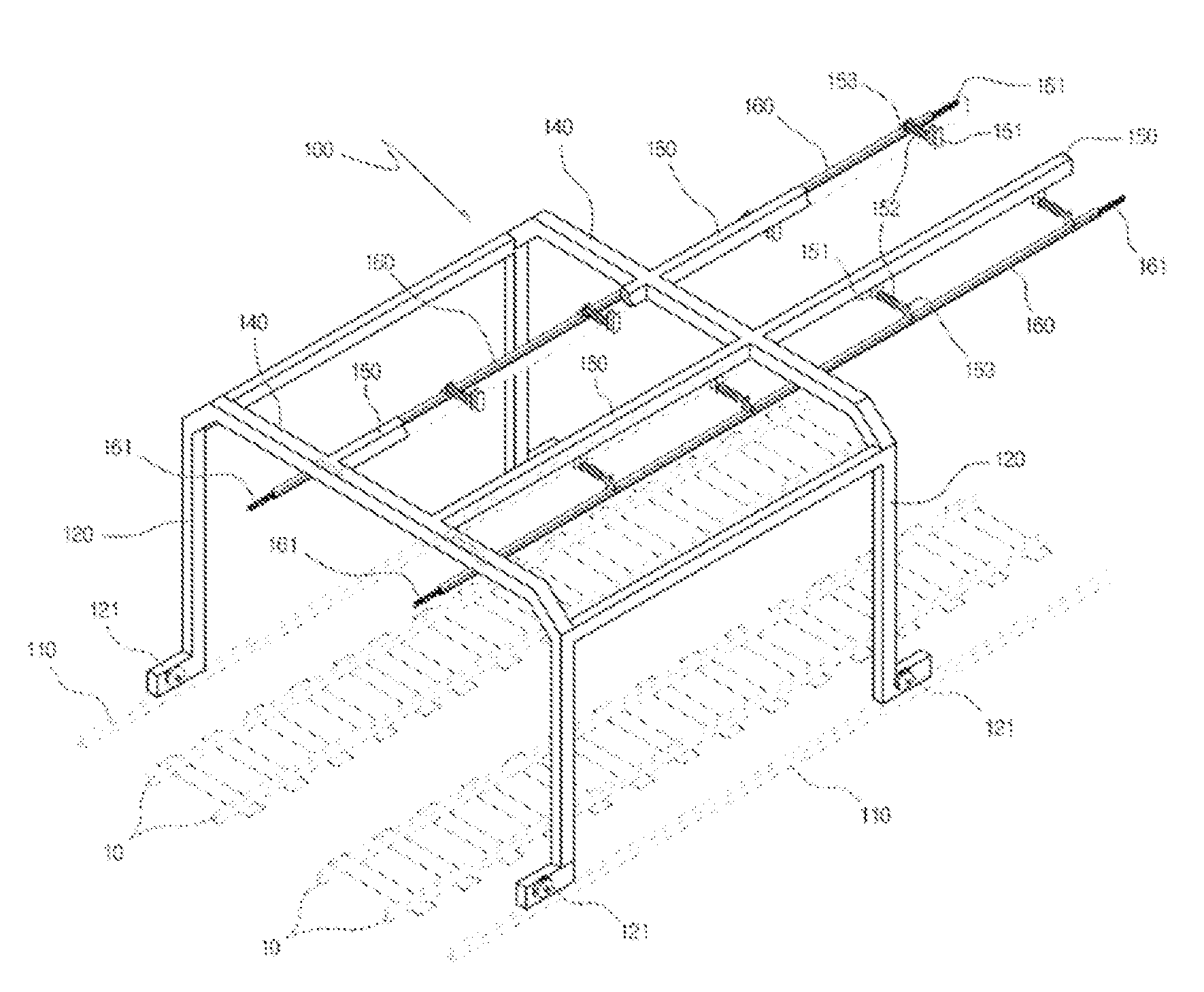
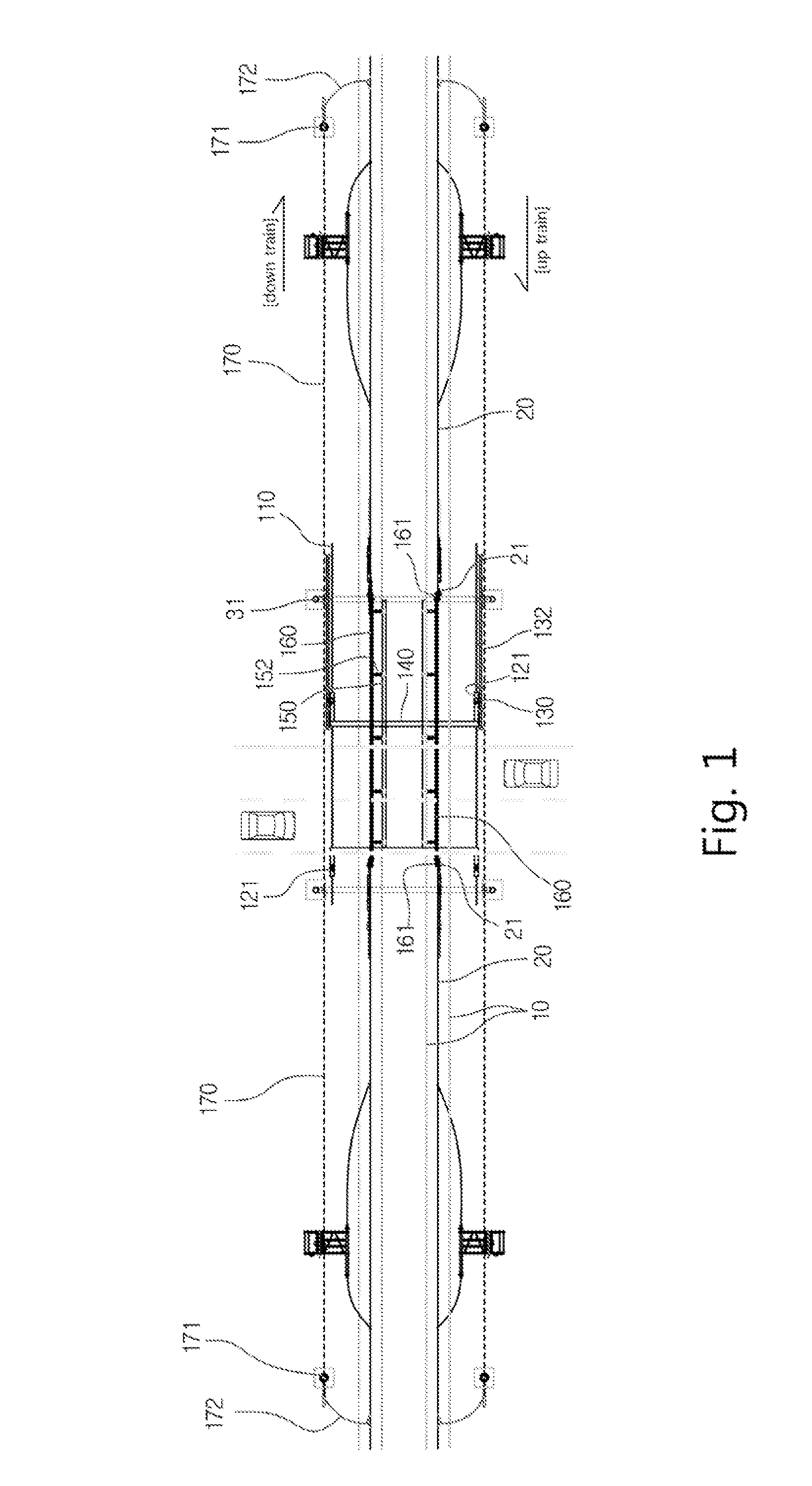
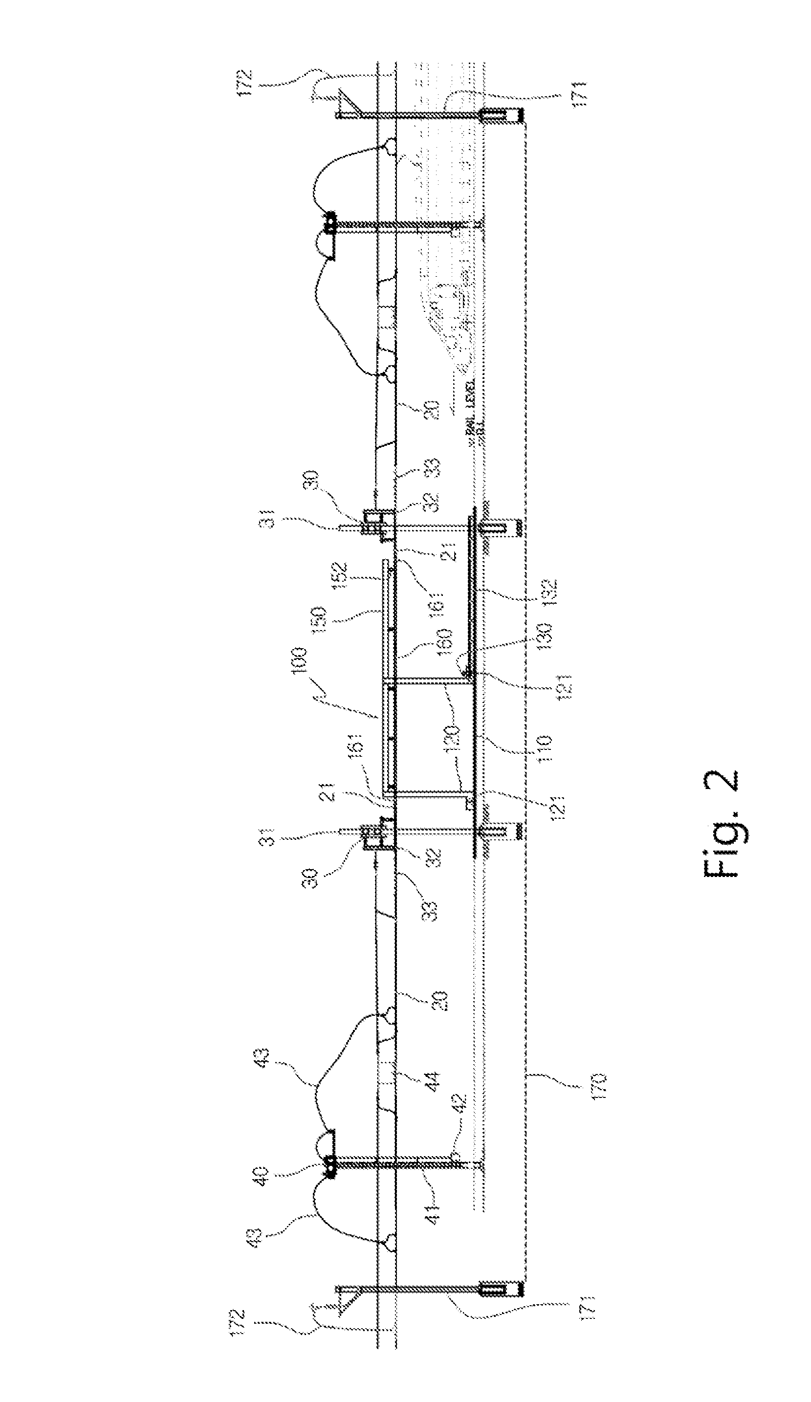
[0036]FIG. 1 is a schematic view showing the movable cat nary system at a railway crossing according to the present invention. FIG. 2 is a schematic side view showing the movable catenary system at a railway crossing according to the present invention. FIG. 3 is a schematic front view showing the movable catenary system at a railway crossing according to the present inven...


PUM


Abstract

The present invention provides a gantry type movable catenary system at railway crossing having a simple and reliable structure, which can be applied to a conventional railway crossing as well as to a new railway crossing, and at the same time is improved such that service and maintenance are easy. The gantry type movable catenary system according to the present invention comprises: a pair of auxiliary rails 110 with a fixed length installed in parallel with railway rails 10 from the right and left outsides of the railway rails at the crossing; a frame structure of which a lower end is installed on the auxiliary rail, the frame structure being connected with a drive motor 130 to be reciprocally movable on the auxiliary rail; a movable contact wire 160 with a certain length connected via an insulator 152 On top of the frame structure and installed to parallel to a catenary wire 20; and a control unit which controls driving of the drive motor to operate the positioning of the frame structure, wherein, from a first power connecting section 21 of the catenary wire 20, a second power connecting section 161 of the both ends of the movable contact wire 160 is connected or disconnected depending on reciprocal movement of the frame structure, thus supplying or disconnecting electric power.

Description

CROSS-REFERENCE TO RELATED APPLICATION(S)[0001]This application claims the benefit of Korean Patent Application No. 10-2014-0121137, filed on Sep. 12, 2014, the disclosure of which is hereby incorporated by reference herein in its entirety.BACKGROUND[0002]1. Technical Field[0003]The present invention relates to a catenary system for supplying electricity for the operation of electric locomotives. In particular, the present invention relates to a gantry type movable catenary system which is installed in a railway crossing section to supply electricity for the operation of electric) locomotives, provides connection and disconnection of the catenary or overhead electric wire, and is configured to move reciprocally in lateral directions (along the rail) of the crossing to allow movement of over-height heavy transport vehicles and special motor vehicles and the like or the passing of other electric locomotives.[0004]2. Description of the Related Art[0005]Touted as the new means for trans...

Claims


Application Information

Patent Timeline
Patent Type & Authority Applications(United States)
IPC IPC(8): B60M1/23
CPCB60M1/23B60M1/04B60M1/20B61L29/00
Inventor KIM, YEON, WON
Owner KIM YEON WON
Learn More