Turbomachine rotors with thermal regulation

Active Publication Date: 2016-03-17
RAYTHEON TECH CORP
View PDF3 Cites 7 Cited by
  • Summary
  • Abstract
  • Description
  • Claims
  • Application Information

AI Technical Summary

Benefits of technology

[0018]In addition to one or more of the features described above, or as an alternative to any of the foregoing embodiments, the ape

Problems solved by technology

However, this type of cooling minimally regulates temperature differentials in aft stages of the compressor.
For example, when the engin

Method used


Image

  • Turbomachine rotors with thermal regulation
  • Turbomachine rotors with thermal regulation

Examples


Embodiment Construction

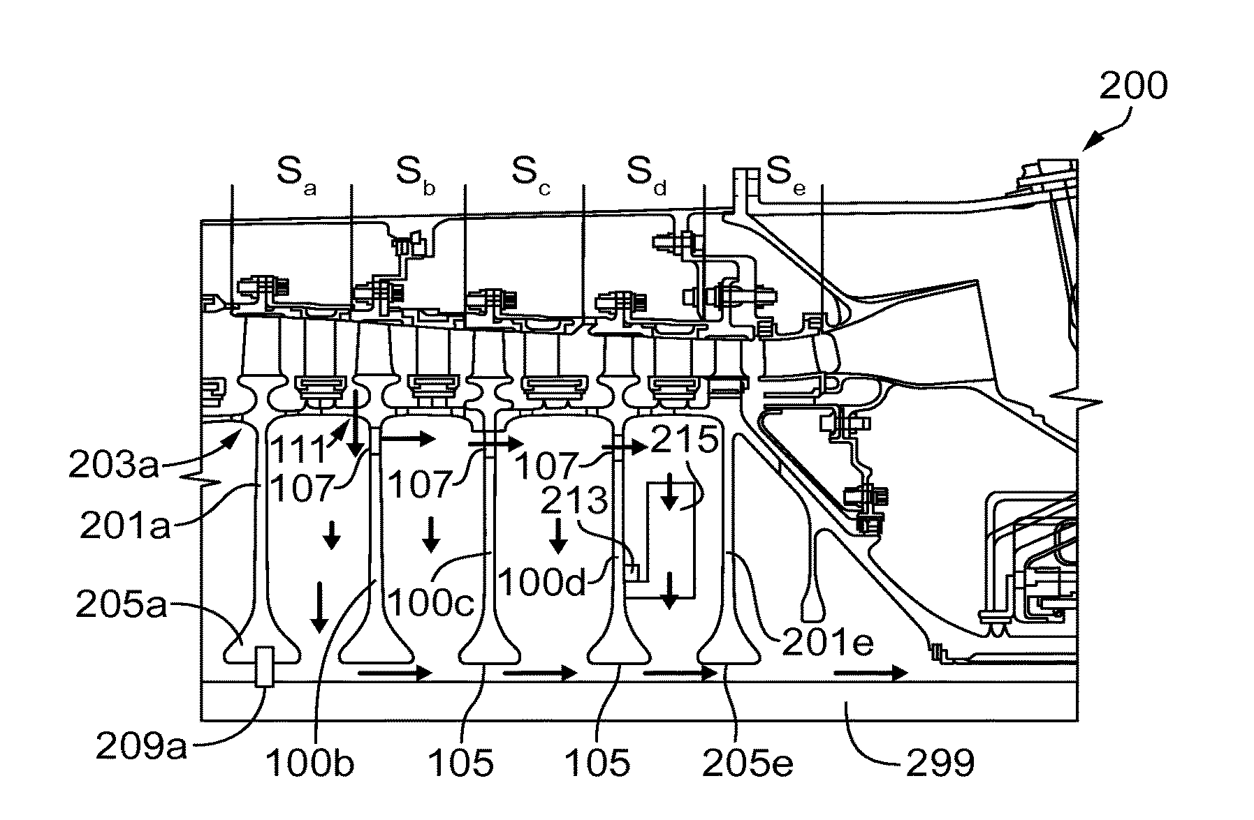
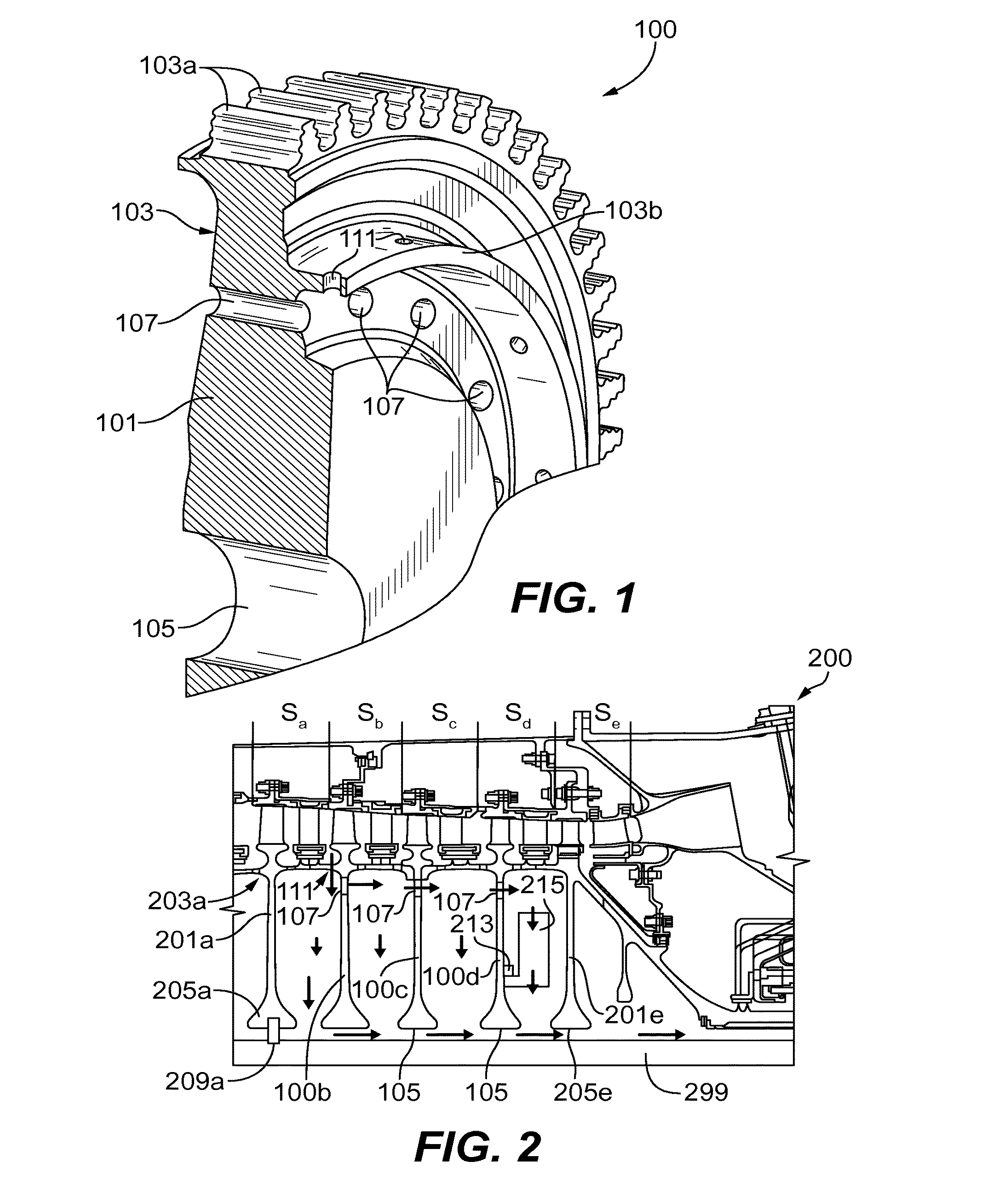
[0039]Reference will now be made to the drawings wherein like reference numerals identify similar structural features or aspects of the subject disclosure. For purposes of explanation and illustration, and not limitation, an illustrative view of an embodiment of a rotor disk in accordance with the disclosure is shown in FIG. 1 and is designated generally by reference character 100. The systems and methods described herein can be used to enhance thermal regulation of portions of a turbomachine (e.g., to reduce rotor disk temperature differential between the rim and the bore).

[0040]In at least one aspect of this disclosure, a rotor disk 100 for a turbomachine (e.g., for the compressor portion) includes a disk body 101, a rim 103 configured to connect to or include a rotor blade disposed on a radially outward portion of the rim 103, and a bore 105 disposed on a radially inward portion of the disk body 101 and configured to be disposed radially adjacent to a shaft such that there is a g...


PUM


Abstract

A rotor disk for a turbomachine includes a disk body, a rim configured to connect to or include a rotor blade disposed on a radially outward portion of the disk body, a bore defined in a radially inward portion of the disk body and configured to be radially adjacent to a shaft, and a thermal regulation aperture defined in the disk body, radially inward of the rim, for allowing flow to pass axially through the disk body when disposed in a stage of a turbomachine, and a thermal regulation aperture defined in the disk body for allowing flow to pass through the disk body when disposed in a stage of a turbomachine.

Description

CROSS REFERENCE TO RELATED APPLICATIONS[0001]This application claims the benefit of U.S. Provisional Patent Application Ser. No. 62 / 049,996, filed Sep. 12, 2014, the entire contents of which are incorporated herein by reference thereto.BACKGROUND[0002]The present disclosure relates to turbomachine components and systems, more specifically components and systems configured for thermal regulation thereof.[0003]Turbomachine compressors include a series of blades connected to rotor disks which are operatively disposed on a shaft to rotate. Each blade has a corresponding stator, which together with the blade, form a stage. The disks can include pathways at the bore portion which connects to the shaft to allow cooling airflow to pass through close to the shaft.[0004]Traditionally, a forward stage can include a bleed to allow cool air to flow from the rim of the rotor disk through a rotor cavity, down toward the shaft through the bore, and out to a pressure sink (e.g., turbine). However, t...

Claims


Application Information

Patent Timeline
IPC IPC(8): F01D5/06F01D5/08F01D25/12
CPCF01D5/08F01D5/06F05D2260/20F05D2220/30F05D2240/20F01D25/12F01D5/081F02C7/18F04D29/321F04D29/584
Inventor BINTZ, MATTHEW E.FORCIER, MATTHEW P.HIESTER, PAUL J.
Owner RAYTHEON TECH CORP
Why Eureka
Try Eureka