Vehicle lighting device using a multiple-source optical lens

Active Publication Date: 2016-03-17
VALEO VISION SA
View PDF3 Cites 8 Cited by
  • Summary
  • Abstract
  • Description
  • Claims
  • Application Information

AI Technical Summary

Benefits of technology

[0022]Preferentially, the substrate has a surface for location of the light sources, the surface having a central lead, such that the light sources placed in the end zones of the surface are set back from those placed on the lead relative to the direction of emission of the light by the sources. In other words, each light source placed on an input surface of an end individual portion is further away from the output surface of the same individual portion than the light sources placed on the input surfaces of the intermediate individual portions relative to their corresponding output surfaces. In this way, on a motor vehicle, the end light sources will be able to provide an intense

Problems solved by technology

Such a device does however present the drawback of implementing a number of individual assemblies, and therefore a number of separ

Method used


Image

  • Vehicle lighting device using a multiple-source optical lens
  • Vehicle lighting device using a multiple-source optical lens
  • Vehicle lighting device using a multiple-source optical lens

Examples


Embodiment Construction

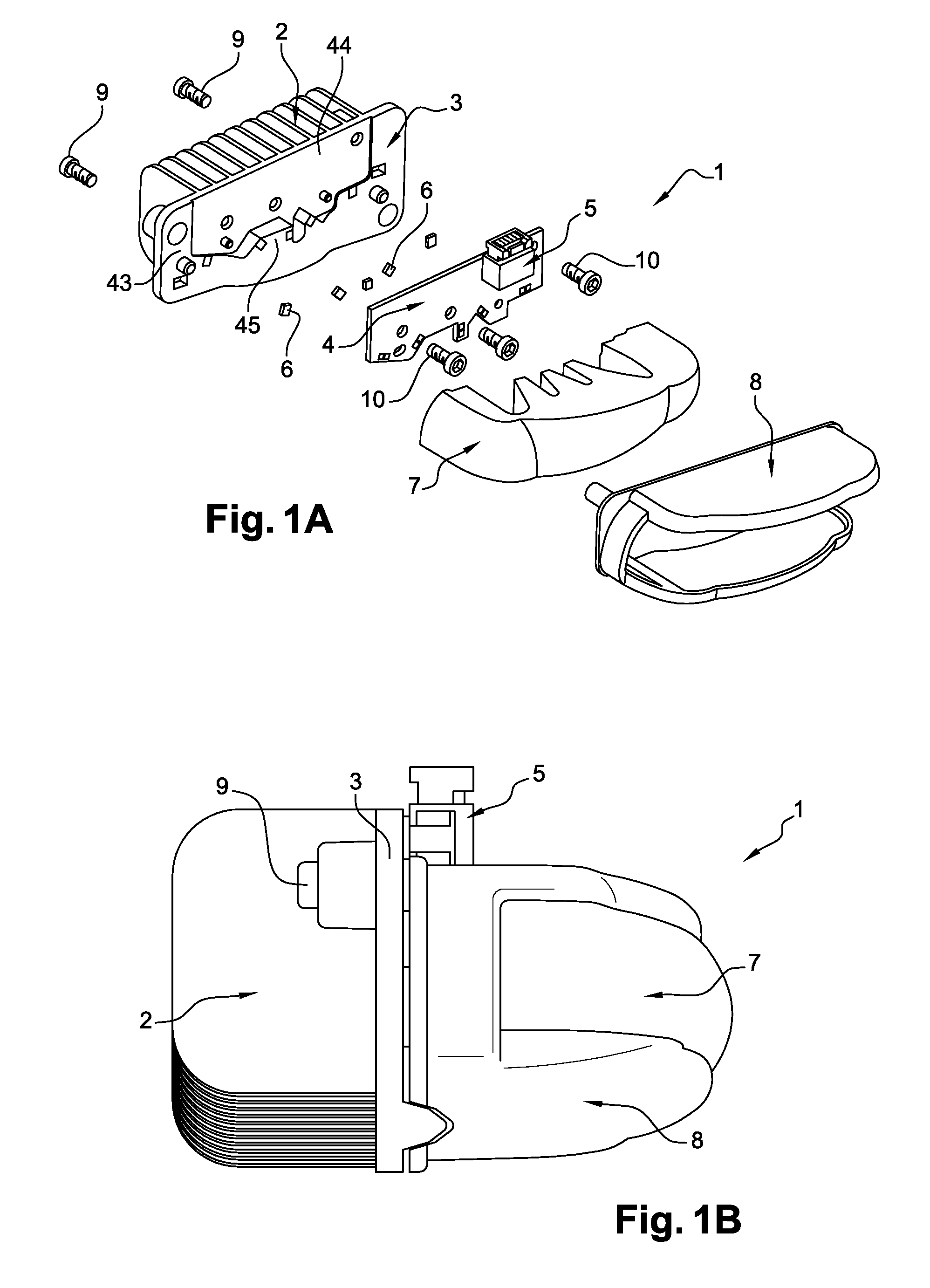
[0055]Referring to FIGS. 1A and 1B, a light module 1 according to the invention comprises a heat sink 2 linked to a substrate 3, an electronic card 4 provided with an electrical connector 5, five light-emitting diodes 6 which are called LEDs herein below in the description, a part 7 made of transparent material according to the invention and a protecting and securing housing 8, suitable for gripping the transparent part 7. The housing 8 is fixed to the substrate 3 by means of a first series of screws 9. The electronic card 4 is anchored in the substrate 3 by means of a second series of screws 10. Such a light module 1 is intended to be fixed, for example, inside a vehicle headlight.

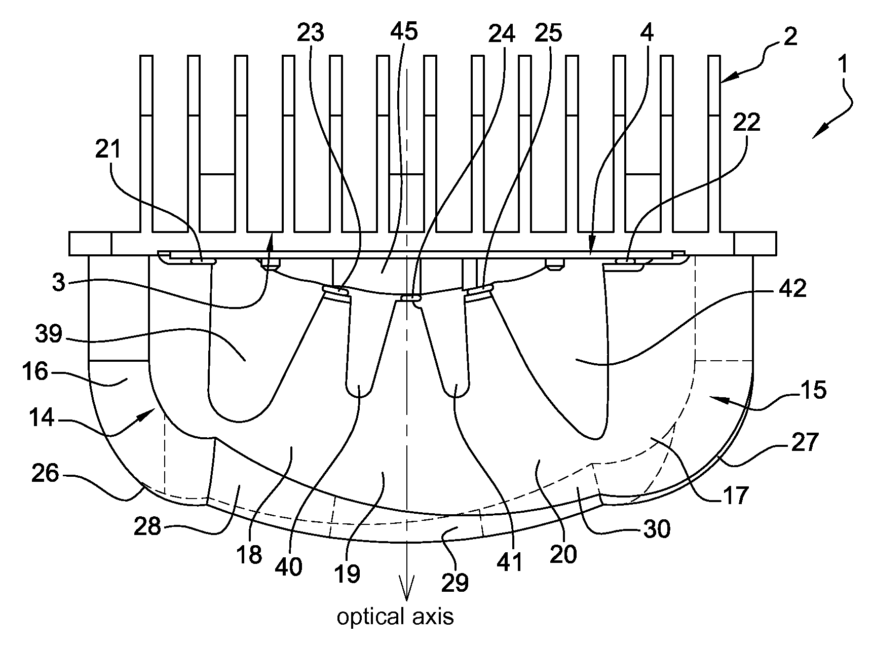
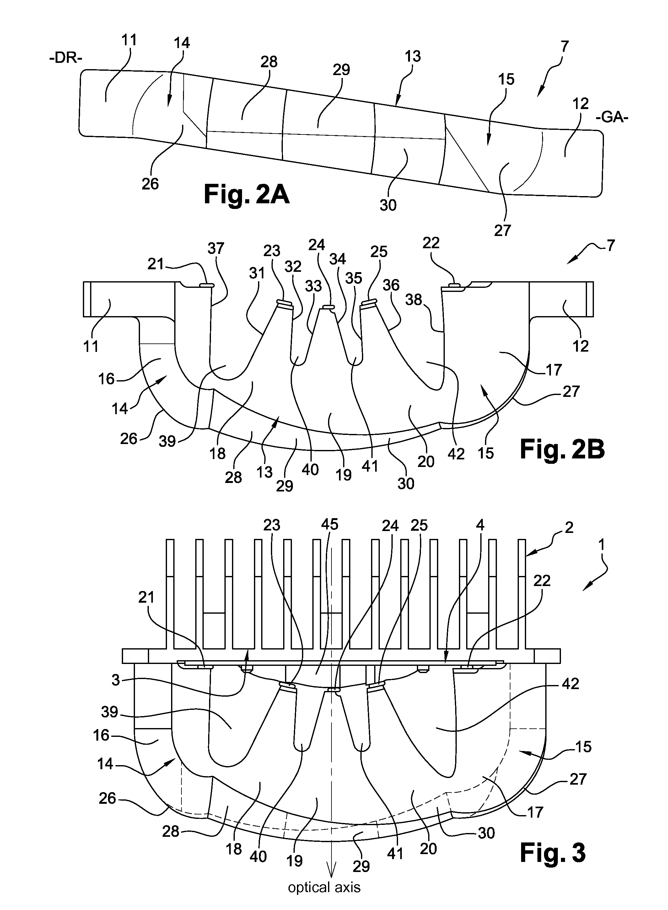
[0056]Referring to FIGS. 2A, 2B and 3, the transparent part 7 made of transparent material according to the invention is solid and is made of PVC (polyvinyl chloride), and acts as an optical lens. This transparent part 7 schematically comprises two lateral tabs 11, 12 and a central body 13 situated betwee...


PUM


Abstract

A part made of transparent material comprising at least two individual portions each consisting of an input surface and an output surface, the output surface being focused on the input surface of the same portion, the output surfaces being contiguous so as to form an overall output surface of the part which is continous.
Furthermore, the input surfaces are at a distance from one another by being separated by means suitable for preventing rays from a light source placed on the input surface of a portion from being able to pass through the output surface of the adjacent individual portion.

Description

CROSS-REFERENCE TO RELATED APPLICATIONS[0001]This application claims priority to the French application 1458689 filed on Sep. 16, 2014, which application is incorporated herein by reference and made a part hereof.BACKGROUND OF THE INVENTION[0002]1. Field of the Invention[0003]The invention relates to a vehicle lighting device using a multiple-source optical lens.[0004]2. Description of the Related Art[0005]Lighting devices intended to be mounted in vehicle headlights exist and have already been the subject of patents. The patent application U.S. 2007 / 0120137, which is now issued as U.S. Pat. No. 7,560,742 can for example be cited, which relates to a multiple-source lighting device comprising a multiplicity of individual and distinct assemblies. Each assembly comprises a light source which is mounted on a substrate supplying current to the source, and a lens associated with the source. All the light emitted by this light source is transmitted to an output diopter of the lens, via a d...

Claims


Application Information

Patent Timeline
IPC IPC(8): F21S8/10F21W107/10
CPCF21S48/1275F21S48/1291F21S48/1154F21V5/045F21S41/151F21S41/19F21S41/26F21S41/27F21S41/29F21S41/663F21S43/14F21S43/26F21S43/27F21S45/48F21S41/143F21S41/24F21S41/25F21S41/265F21S43/19F21S43/241F21S43/243F21S43/249
Inventor MEYRENAUD, JEAN-LUC
Owner VALEO VISION SA
Why Eureka
Try Eureka