Configurable Solenoid Actuation Method and Apparatus

a technology of connectorized apparatus and solenoid, which is applied in the direction of relays, magnets, magnetic bodies, etc., can solve the problems of increasing the electrical resistance of the circuit, increasing the number of additional components, and generating excessive energy consumption and heating in the solenoid coil. , to achieve the effect of preventing unintended opening of the solenoid, reducing the number of additional components, and high efficiency power supplies

Inactive Publication Date: 2016-03-17
X 10
View PDF1 Cites 2 Cited by
  • Summary
  • Abstract
  • Description
  • Claims
  • Application Information

AI Technical Summary

Benefits of technology

The present invention is a configurable connectorized method and apparatus for driving a solenoid coil that can provide a high force to move the solenoid from its fully open position to its sealed position. The invention reduces energy consumption and heating of the solenoid coil when the solenoid is sealed. It also facilitates detection of a solenoid coil that is open or shorted, and can reduce the current on a solenoid for which the armature is jammed. The invention simplifies connections to one or more relays or solenoids without the requirement for additional components such as diodes. The invention allows determination of whether a solenoid is sealed without the need for auxiliary electrical contacts, and can use information about the solenoid unsealed state to instantly increase the force on the solenoid armature to cause it to return to its sealed position before it has moved significantly. When compared with traditional industrial control input / output modules, the configurable, connectorized input / output module reduces the number of additional components required such as power supplies and terminal blocks. The invention allows high efficiency power supplies to be used. The present invention addresses the inductive current at turn-off and provides two ways to handle it, both without adding components. No additional components are required to provide for safe circuit operation.

Problems solved by technology

However, as described in detail below, there are significant challenges associated with driving solenoids in an energy efficient manner with circuitry that does not itself create further problems.
As is widely known to those skilled in the art of solenoid-driven mechanism design, there is a delicate balance between providing sufficient solenoid force at a desired distance of travel and generating excessive energy consumption and heating in the solenoid coil.
Thus a solenoid that is to remain sealed for a long period of time tends to become hot and consume a large amount of energy compared to what is needed just to hold the solenoid sealed.
However, when the solenoid is fully open, there exists an air gap in the magnetic circuit that significantly increases the electrical reluctance of the circuit, said reluctance being the ratio of magnetomotive force (MMF) to magnetic flux developed.
Energy is being wasted.
Unfortunately, the circuit of Suzuki requires that a series-wired transistor throttle the current to the relay coil thus creating heat and reducing the possible energy savings considerably.
Unfortunately, another ¼ of said energy is burned up in ohmic losses in the transistor.
Unfortunately, however, PWM can easily generate disruptive electrical radiation unless special care is taken.
In an industrial control system application it is almost unthinkable to place restrictions on the user of a solenoid.
Unfortunately, said integrated circuits can produce undesirable electrical interference as described earlier.
For example, an application note for the Texas Instruments DRV102 states, “The PWM switching voltages and currents can cause electromagnetic radiation.” The note further suggests that determining the location of noise reducing components “may defy logic”, i.e. may be difficult to predict and require repetitive empirical testing.
The prior art has not adequately addressed a significant design challenge in solenoid driving: how to determine if a solenoid is sealed.
The solenoid may be jammed and unable to initially move in either direction.
The solenoid coil may be open or not electrically continuous and therefore incapable of generating the required magnetic field.
Or, there could be a momentary loss of electrical current that results in the solenoid holding force being reduced briefly.
However, if the solenoid 10 is not a relay, then said solenoid 10 must be mechanically connected to said auxiliary contact 92, such connection being problematic and costly.
This requirement is prohibitive except for the most critical solenoid systems.

Method used


Image

  • Configurable Solenoid Actuation Method and Apparatus
  • Configurable Solenoid Actuation Method and Apparatus
  • Configurable Solenoid Actuation Method and Apparatus

Examples


Embodiment Construction

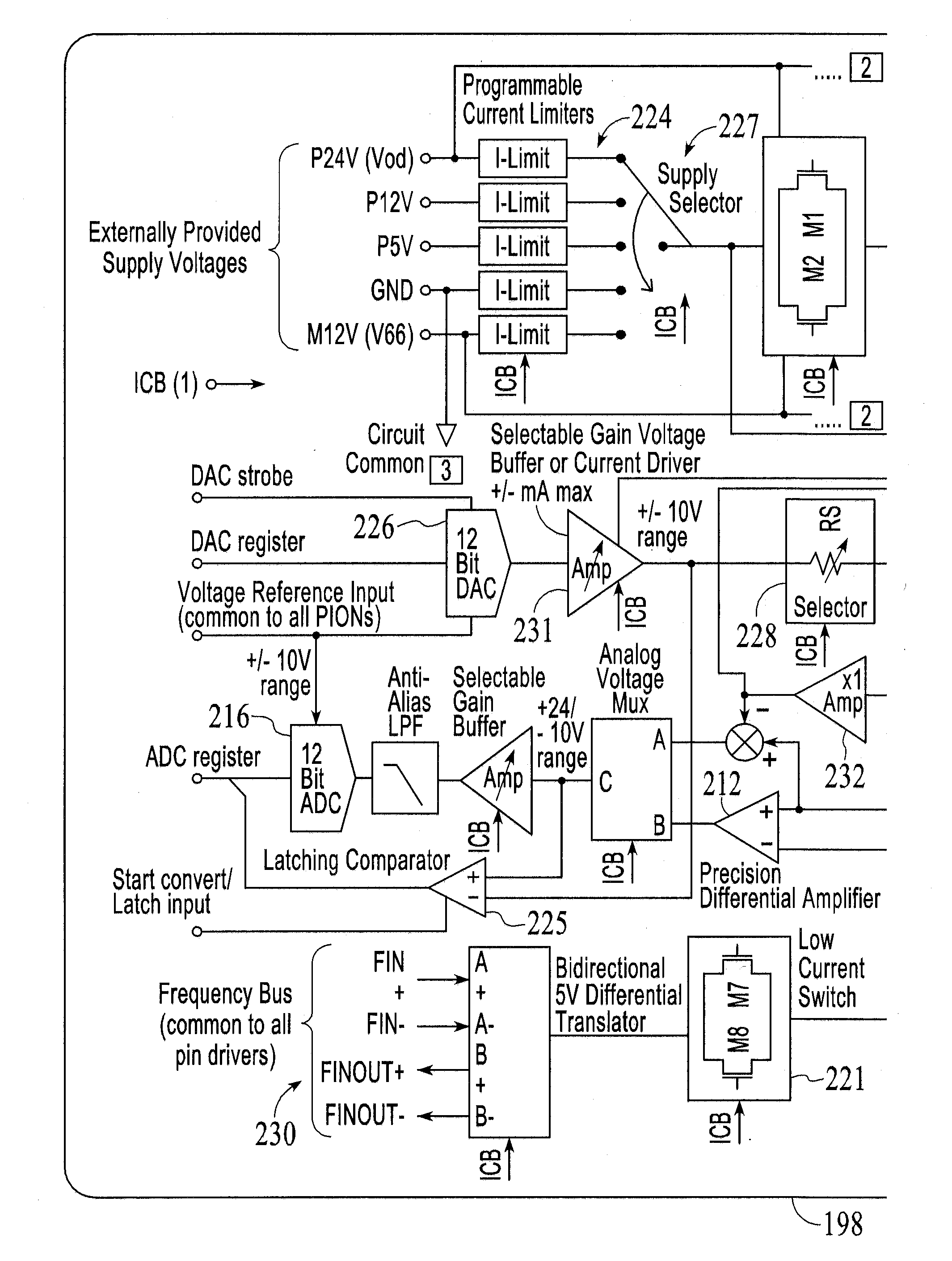
[0037]FIG. 6 depicts a functional block diagram of the configurable connectorized input / output module 15 of the present invention. Included inside said module 15 of the preferred embodiment is a microprocessor 80 which is capable of directing any of a plurality of signals to one or more pins 16 which are subsequently to be connected to various sensors and actuators such as solenoid, but by no means limited to solenoids. In particular, said configurable connectorized input / output module 15 contains one or more power supplies 81 which may be routed in the same manner as other of the plurality of signals via switching means 82 such as R5 or R6 and connect to one or more connector pins 16. When a solenoid is connected between two such pins 16, the configurable connectorized input / output module 15 can produce one of a plurality of power levels to said solenoid thereby adjusting the current flowing through the solenoid without the need for PWM.

[0038]The configurable input / output module 15...


PUM

PropertyMeasurementUnit
power levelsaaaaaaaaaa
activation-level voltageaaaaaaaaaa

Abstract

A configurable, connectorized method and apparatus for driving a solenoid coil reduces energy consumption and heating of the solenoid coil, allows detection of the solenoid state, and simplifies connections to the solenoid.

Description

RELATED APPLICATIONS[0001]This application claims the benefit of U.S. Provisional Patent Application Ser. No. 61 / 406,414 filed Oct. 25, 2010, and is a continuation-in-part of U.S. patent application Ser. No. 13 / 069,292 filed Mar. 22, 2011 (which claims the benefit of U.S. Provisional Patent Application Ser. No. 61 / 316,070 filed Mar. 22, 2010), which is a continuation-in-part of U.S. patent application Ser. No. 12 / 911,445 filed Oct. 25, 2010 (now abandoned), which is a continuation of U.S. patent application Ser. No. 12 / 106,968 filed Apr. 21, 2008 (now U.S. Pat. No. 7,822,896 and which claims the benefit of U.S. Provisional Application Ser. No. 60 / 950,040 filed Jul. 16, 2007), which is a continuation-in-part of U.S. patent application Ser. No. 11 / 801,127 filed May 7, 2007 (now abandoned), which is a continuation of U.S. patent application Ser. No. 11 / 296,134 filed Dec. 6, 2005 (now U.S. Pat. No. 7,216,191), which is a continuation-in-part of U.S. patent application Ser. No. 11 / 043,29...

Claims


Application Information

Patent Timeline
Patent Type & Authority Applications(United States)
IPC IPC(8): H01F7/06
CPCH01F2007/062H01F7/064H01F7/1805
Inventor SAGUES, PAULBOTHA, MAURITZBRASFIELD, LARRY
Owner X 10
Why Eureka
Try Eureka