Horn apparatus

a horn and horn technology, applied in the field of horn apparatuses, can solve the problems of easy generation of disturbance of air flow, and achieve the effect of smoothing air flow in the air flow channel and suppressing variations in acoustic characteristics of the horn apparatus

Active Publication Date: 2016-03-17
MITSUBA CORP
View PDF5 Cites 8 Cited by
  • Summary
  • Abstract
  • Description
  • Claims
  • Application Information

AI Technical Summary

Benefits of technology

[0010]According to the present invention, at least either one of the outer peripheral portion and the inner peripheral portion forming the air flow channel is the inclined surface having the diameter which is gradually reduced as the inclined surface gets away from the diaphragm in the axial direction of the movable iron core. Therefore, compared with the conventional step-shaped air flow channel having vertical surfaces, air flow in the air flow channel can be smoothened. Therefore, disturbance of air flow in the air flow channel is not easily generated, and variations in acoustic characteristics of the horn apparatus can be suppressed.

Problems solved by technology

Therefore, the horn apparatus encounters a problem that disturbance of air flow is easily generated during operations and variations are easily generated in acoustic characteristics.

Method used


Image

  • Horn apparatus
  • Horn apparatus
  • Horn apparatus

Examples


Embodiment Construction

[0025]Hereinafter, a first embodiment of the present invention will be described in detail with reference to the accompanying drawings.

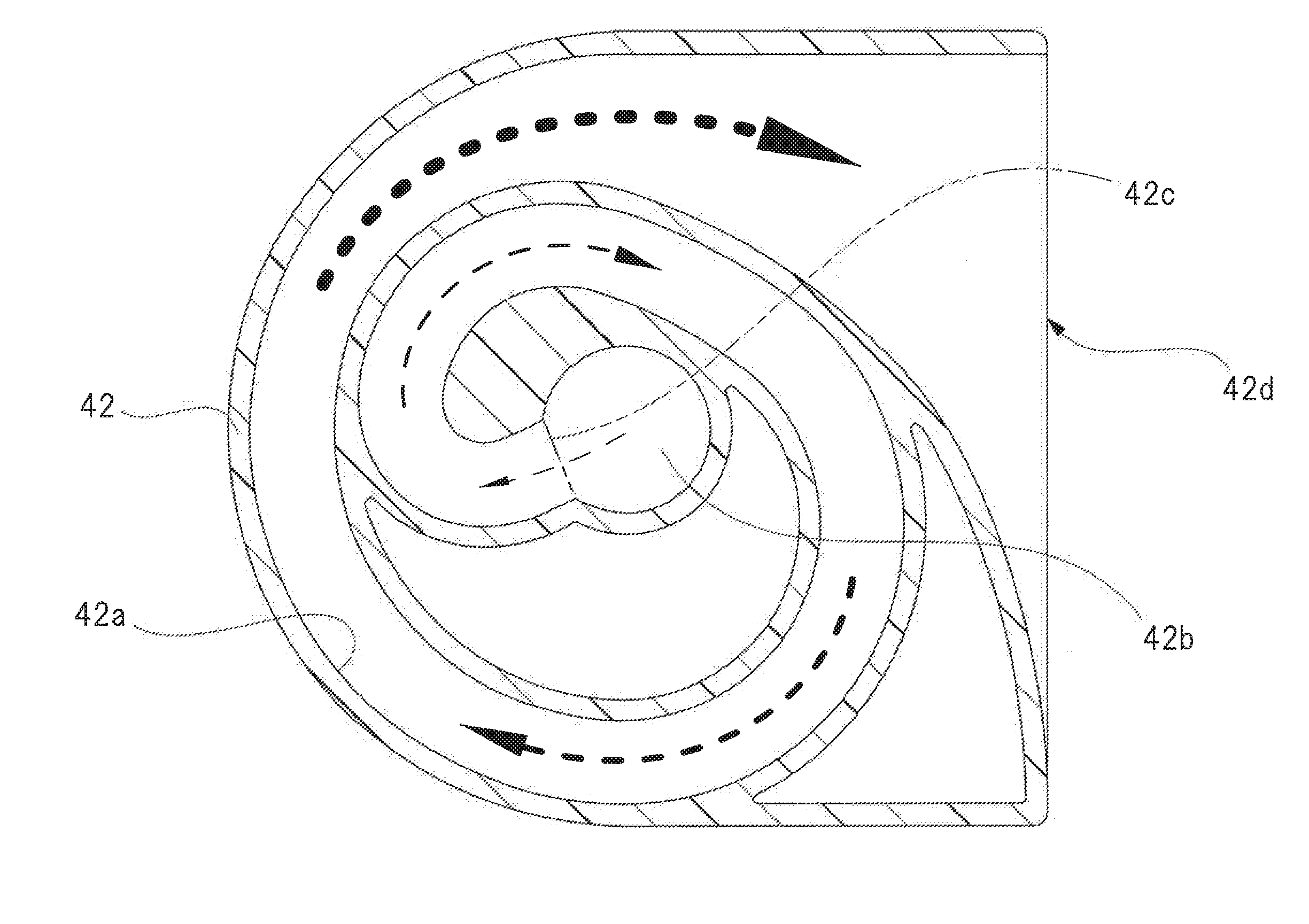
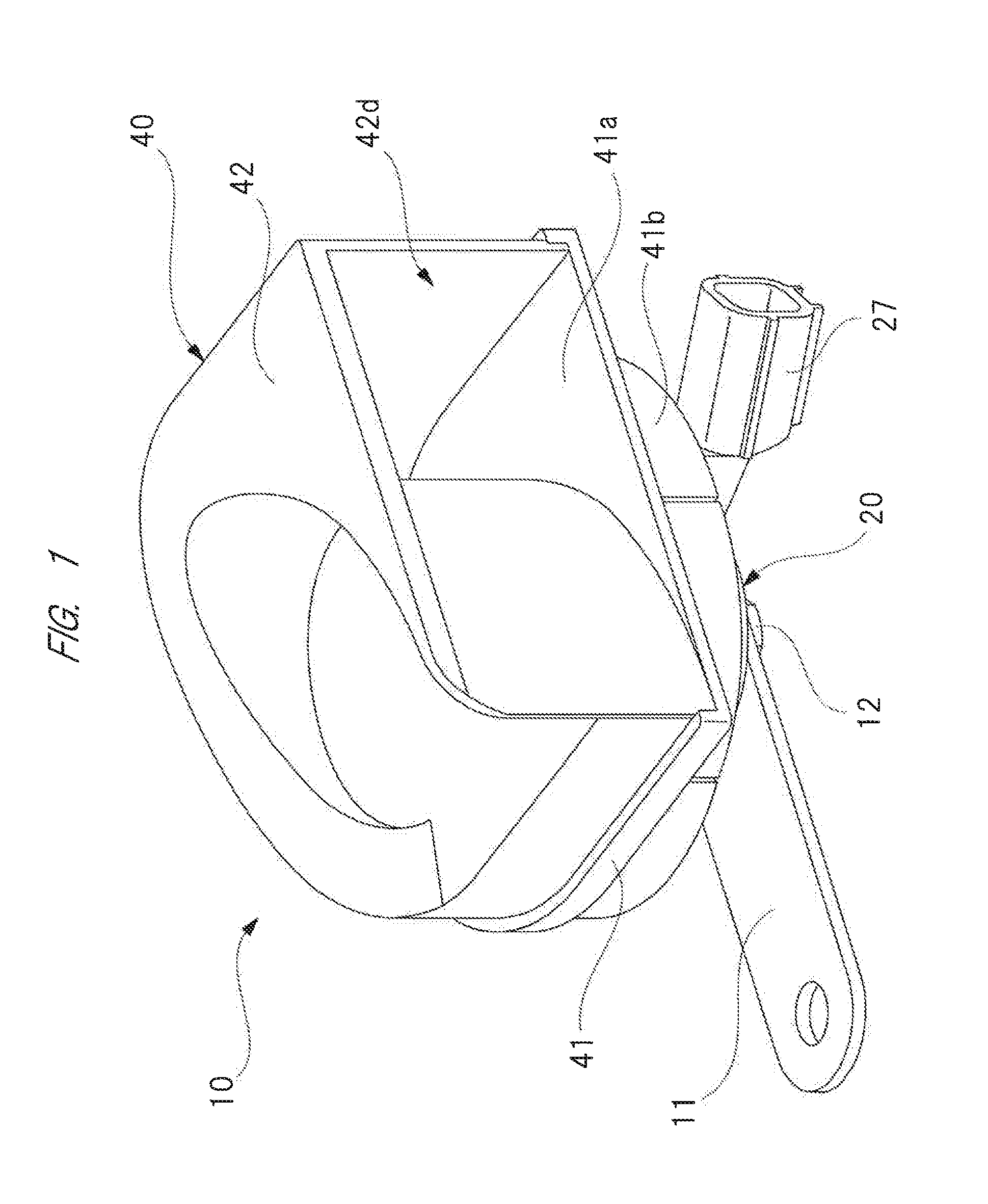
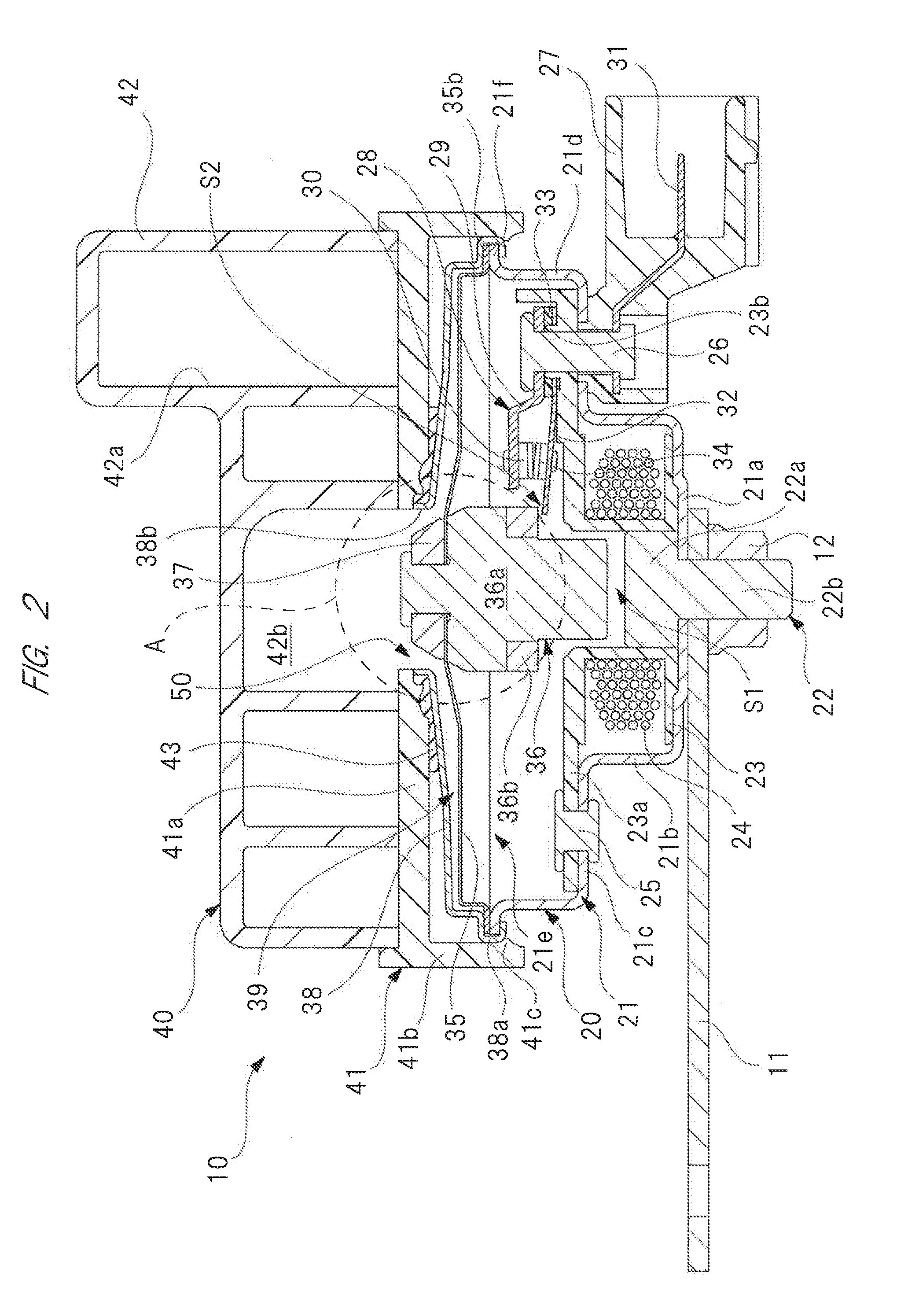
[0026]FIG. 1 is a perspective view showing a horn apparatus of the present invention, FIG. 2 is a cross-sectional view showing an internal structure of the horn apparatus of FIG. 1, FIG. 3 is an enlarged cross-sectional view showing a portion “A” surrounded by a broken-line circle in FIG. 2, FIG. 4 is a cross-sectional view showing an internal structure of a resonator of FIG. 2, FIG. 5A is a simulation view showing a pressure distribution at the time of suction, FIG. 5B is a simulation view showing a pressure distribution at the time of discharge, FIG. 5C is a simulation view showing a flow rate of air discharged from an air vibrating chamber to the resonator, FIGS. 6A-6C are simulation drawings of conventional techniques corresponding to FIGS. 5A-5C, FIG. 7A is a comparison graph explaining variation improvement of a sound pressure level [dB (A)], a...


PUM


Abstract

It is an object of the present invention is to smoothen air flow at the time of vibrations of the diaphragm, and to suppress variations in acoustic characteristics. Since the inclined surface 37c of the washer 37, which forms the air flow channel 50, is an inclined surface having a diameter gradually reduced with distance from the diaphragm 35 in the axial direction of the movable iron core 36, compared with the conventional step-shaped air flow channel having vertical surfaces, air flow in the air flow channel 50 can be smoothened. Therefore, disturbance in air flow is not easily generated in the air flow channel 50, and variations in acoustic characteristics of the horn apparatus 10 can be suppressed.

Description

CROSS-REFERENCE TO RELATED APPLICATION[0001]The present application claims priority from Japanese Patent Application No. JP2014-186478 filed on Sep. 12, 2014, the content of which is hereby incorporated by reference into this application.TECHNICAL FIELD OF THE INVENTION[0002]The present invention relates to a horn apparatus for resonating a sound generated by vibrations of a diaphragm with a resonator.BACKGROUND OF THE INVENTION[0003]An electromagnetic type horn apparatus is mounted in a front side of a vehicle such as automotive vehicle. As one example, an electromagnetic type horn apparatus for resonating a sound generated by vibrations of a diaphragm with a resonator is known. Such a horn apparatus provided with a resonator is described in, for example, Japanese Patent No. 5058912 (FIG. 1). The horn apparatus described in Japanese Patent No. 5058912 (FIG. 1) is provided with a case having a bottomed tubular shape, an electromagnet (a coil and a fixed iron core) provided in the ca...

Claims


Application Information

Patent Timeline
Patent Type & Authority Applications(United States)
IPC IPC(8): H04R1/28
CPCH04R1/2865H04R1/30H04R2499/13B60C5/00B60C5/008B60Q5/00B60Q5/008H04R3/04
Inventor KOBAYASHI, YOSHIKAZUYOKOYAMA, HIROSHIMATSUKURA, RYOTA
Owner MITSUBA CORP
Why Eureka
Try Eureka