Sole Structure for a Shoe

a technology for soles and shoes, applied in the field of sole structures, can solve the problems of easy deterioration of the cushioning properties of the midsole, and achieve the effect of improving the flexibility of the sole structure and easy deformation elastically

Inactive Publication Date: 2016-03-24
MIZUNO CORPORATION
View PDF14 Cites 11 Cited by
  • Summary
  • Abstract
  • Description
  • Claims
  • Application Information

AI Technical Summary

Benefits of technology

[0008]According to the first aspect of the present invention, since the plate having the upwardly convexly curved shape is provided at the rear foot region of the sole structure, deterioration of cushioning performance of the rear foot region of the sole structure can be prevented. Also, since the front end of the plate is disposed at the front end of the rear foot sole and the gap is formed in front of the front end of the plate between the front end of the rear foot sole and the rear end of the forefoot sole, a forward movement of the front end of the plate at the time of deformation of the plate is not hindered by the sole thereby allowing for a smooth deformation of the plate to improve cushioning properties. Moreover, the gap formed in front of the front end of the plate facilitates bending deformation of the rear foot sole relative to the forefoot sole thus enhancing flexibility.
[0030]According to the second aspect of the present invention, the plate provided at the rear foot sole of the sole structure can prevent deterioration of cushioning performance of the rear foot sole. Also, since there is formed a gap without the rear foot sole in front of the front end of the plate, a forward movement of the front end of the plate at the time of deformation of the plate is not hindered by the sole thereby allowing for a smooth deformation of the plate to improve cushioning properties. Moreover, the gap formed in front of the front end of the plate facilitates bending deformation of the rear foot sole relative to the forefoot sole thus enhancing flexibility.

Problems solved by technology

As a result, there is a risk that cushioning properties of the midsole easily become deteriorated.

Method used


Image

  • Sole Structure for a Shoe
  • Sole Structure for a Shoe
  • Sole Structure for a Shoe

Examples


embodiment 1

Alternative Embodiment 1

[0079]In the above-mentioned embodiment, an example was explained in which the heel part of the plate 4 is formed in a heel-cup shape by providing the upraised portion 41 at the region extending from the heel rear end of the body portion 40 of the plate 4 to the heel medial and lateral sides, but the application of the present invention is not limited to such an embodiment. Of the entire upraised portion 41 of the body portion 40, the upraised portion 41 provided at the heel rear end may be omitted.

[0080]In the event that the upraised portion 41 is provided at the heel rear end of the plate 4, when impact load in the forward direction is applied to the plate 4 at the time of impacting the ground the upraised portion 41 at the heel rear end may interfere with the heel rear end surface of the upper sole 2A and the forward movement of the plate 4 may be restricted. However, by removing the upraised portion at the heel rear end of the plate 4, the forward movemen...

embodiment 2

Alternative Embodiment 2

[0081]In the above-mentioned embodiment, as a preferred embodiment, an example was shown where the plate 4 extends along the rear foot region from the heel part H to the midfoot part M of the sole structure 1. However, at the heel part H, the plate 4 has only to be placed to cover the position directly under at least the calcaneus CA, and at the midfoot part M, the plate 4 has only to be placed at the position to cover at least the proximal portions of the first to fifth metatarsus MB1 to MB5. This is for receiving the shock load securely at the time of heel contact and midfoot contact during running. The present invention also has application to the structure where the plate 4 is provided either at the heel part H only or at the midfoot part M only.

[0082]In the event that the plate 4 is provided only at the heel part H, for example, the plate 4 is provided along the heel portion of the rear foot sole 2B (to cover the position directly under at least the calc...

embodiment 3

Alternative Embodiment 3

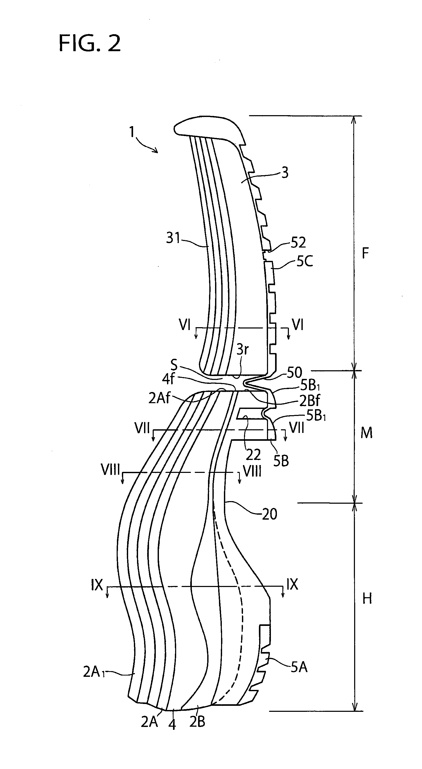
[0083]In the above-mentioned embodiment, an example was shown where the connection 50 has a single bent portion of an inverted V-shape or U-shape (see FIGS. 2, 3, 5), but the present invention also has application to the case in which the connection 50 has a plurality of bent portions of inverted V-shapes or U-shapes. In this case, the connection 50 is bent in a bellows-shape as viewed from the side thereof.


PUM


Abstract

The invention provides a sole structure that can not only prevent deterioration of cushioning performance and improve cushioning properties but also enhance flexibility. The sole structure 1 includes a rear foot sole 2 disposed at a rear foot region of the sole structure 1, a forefoot sole 3 disposed at a forefoot part F of the sole structure 1, and a plate 4 disposed at the rear foot region of the sole structure 1 and having an upwardly convexly curved shape along a heel part H to a midfoot part M of the sole structure 1. A front end portion 4f of the plate 4 is disposed at a front end portion 2Af, 2Bf of the rear foot sole 2 (i.e. upper and lower soles 2A, 2B). There is formed a gap S in front of the front end portion 4f of the plate 4 between the front end portion 2Af, 2Bf of the rear foot sole 2 and a rear end portion 3r of the forefoot sole 3.

Description

TECHNICAL FIELD[0001]The present invention relates generally to a sole structure for a shoe, and more particularly, to an improved sole structure that can prevent deterioration of cushioning performance to improve cushioning properties and that can enhance flexibility.BACKGROUND ART[0002]As a sole structure for a shoe that can prevent deterioration of athletic ability while securing cushioning properties at the time of striking the ground, the applicant of the present invention has proposed such a sole structure as shown in Japanese Patent No. 3308482. Japanese Patent No. 3308482 describes a sole structure in which the wavy corrugated sheet is interposed between the soft elastic upper midsole and the soft elastic lower midsole at least at the heel region of the shoe (see FIG. 1 of JP Pat. No. 3308482).[0003]On the other hand, Japanese Patent No. 4656543 describes a sole structure in which a number of deep indentations are formed on the bottom surface of the midsole at the region ext...

Claims


Application Information

Patent Timeline
Patent Type & Authority Applications(United States)
IPC IPC(8): A43B13/02A43B13/14
CPCA43B13/145A43B13/141A43B13/02A43B13/026A43B13/122A43B13/16
Inventor IUCHI, KAZUNORISATO, NATSUKIKIMURA, TAKAYA
Owner MIZUNO CORPORATION
Why Eureka
Try Eureka