

Turbomachine comprising a casing wear indicator
a technology of casing wear and indicator, which is applied in the direction of machines/engines, mechanical equipment, liquid fuel engines, etc., can solve the problem of engine erosion at a high level
Active Publication Date: 2016-03-24
SAFRAN HELICOPTER ENGINES
View PDF7 Cites 2 Cited by
- Summary
- Abstract
- Description
- Claims
- Application Information
AI Technical Summary
Benefits of technology
The invention allows for easy monitoring of wear in turbine engine parts that cannot be easily reached without disassembling the engine. This helps to determine whether or not to repair the engine, without the need for expensive and time-consuming equipment.
Problems solved by technology
Method used
View moreImage
Smart ImageViewing Examples

Examples
first embodiment
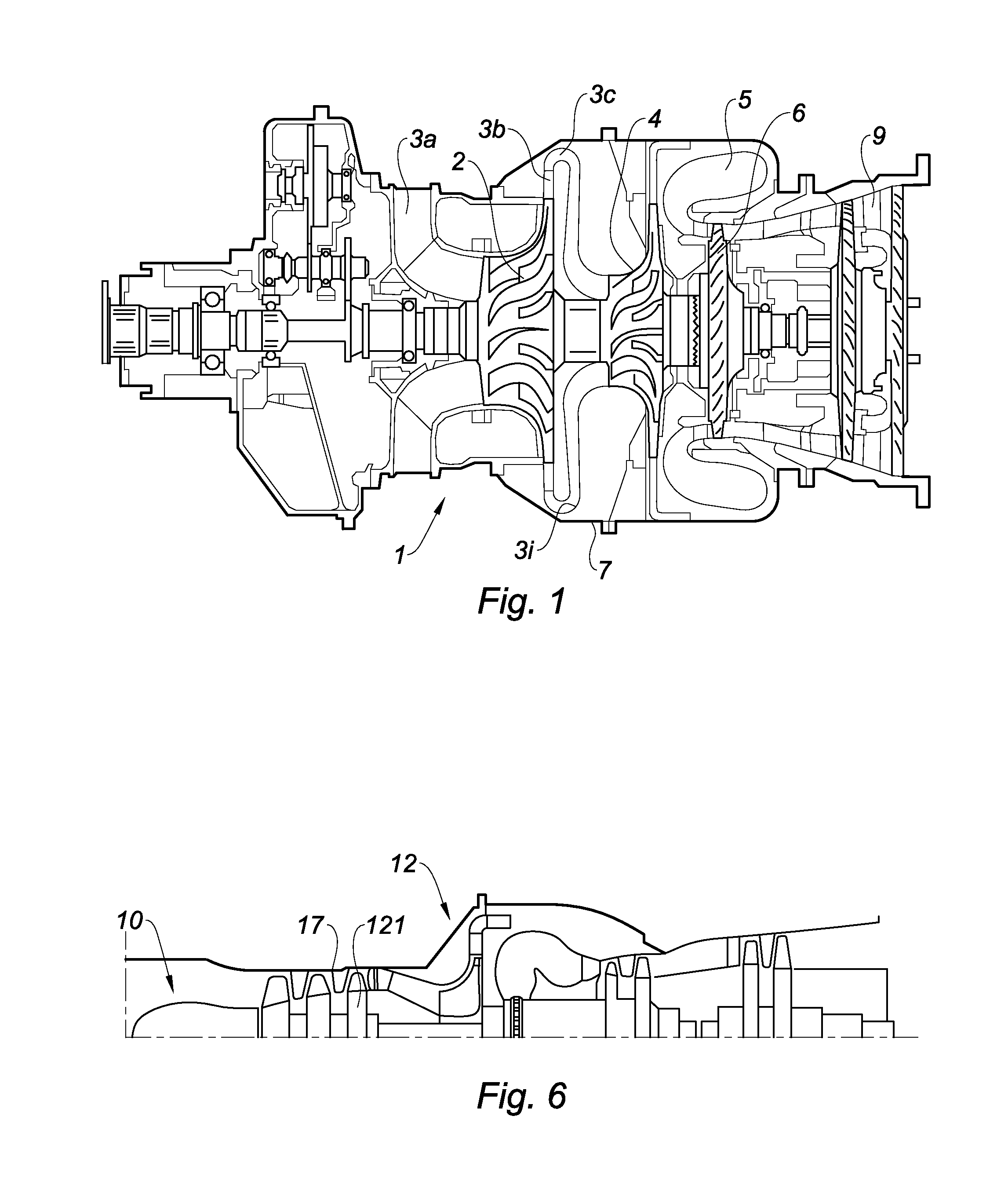
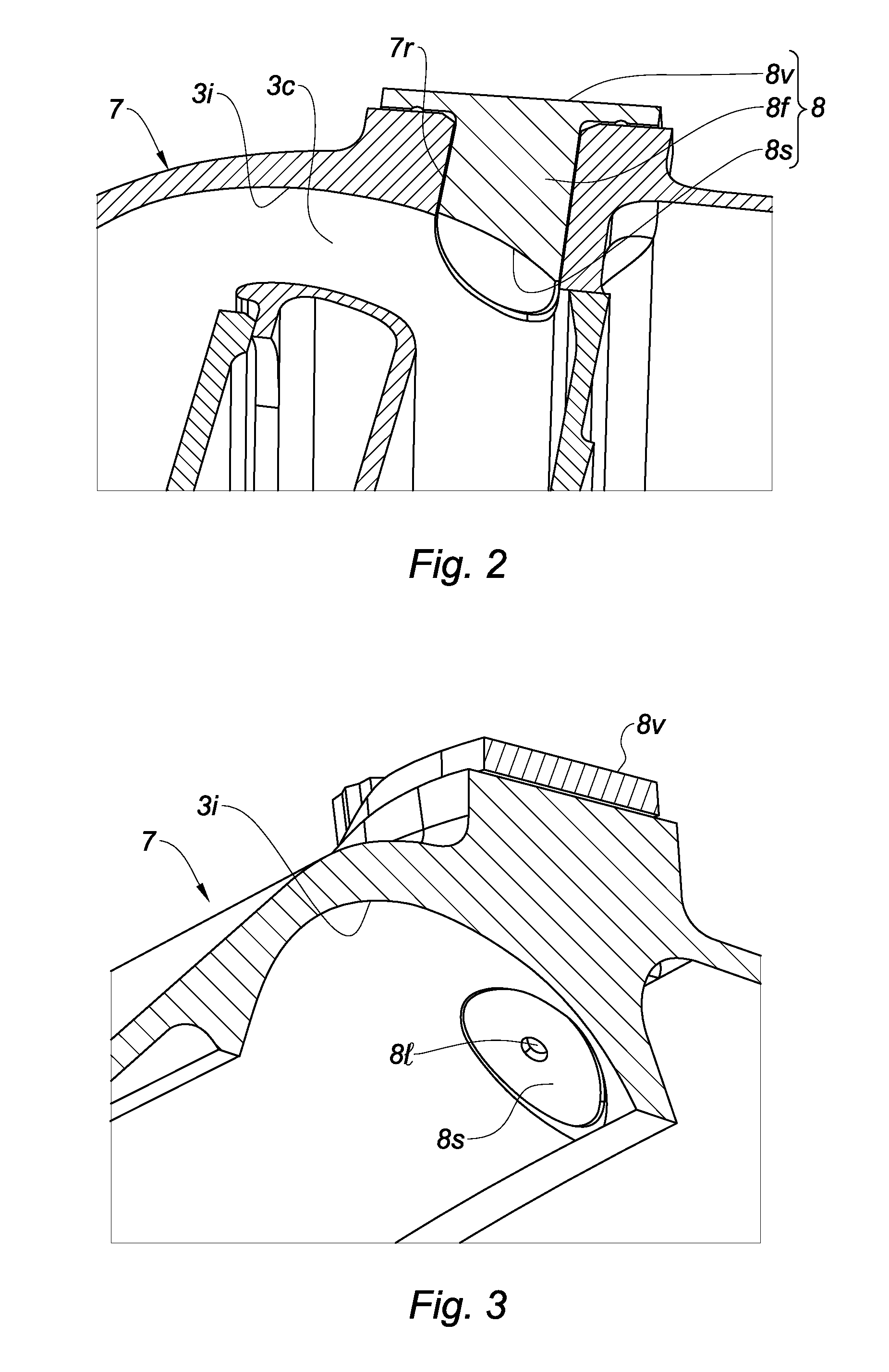
[0024]FIG. 3 is a perspective tangential section along the axis of the engine and viewed from the inside, the detail of the endoscopy stopper in position on the casing having the bore forming the erosion indicator of the invention;
second embodiment
[0025]FIG. 4 shows the detail of the compressor of the engine from FIG. 1, in section in the region of the endoscopy stopper having a wear indicator according to the invention;
[0026]FIG. 5 shows the detail from FIG. 4 without the stopper;
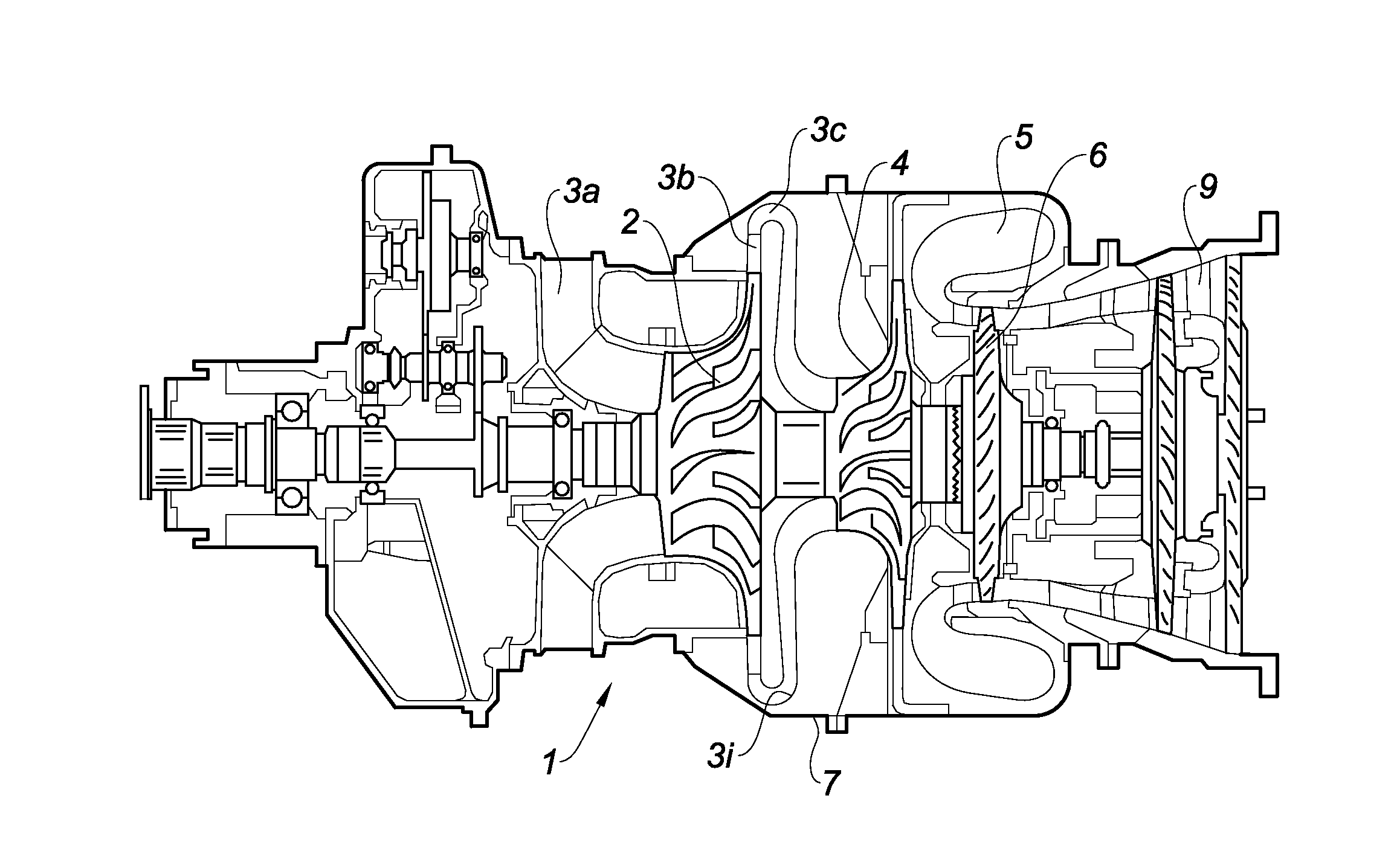
[0027]FIG. 6 shows a gas turbine engine comprising an axial and centrifugal compressor, also according to the invention.
Login to View More PUM
 Abstract
The present invention relates to a turbine engine comprising a casing (7) which has an inner wall (3i) forming a wall of an air duct (3) and at least one opening (7r) passing through the casing, leading into said duct (3) and forming a passage for an endoscope, the opening (7r) being closed during operation of the turbine engine by a stopper (8) which has an end-surface portion (8s) in the extension of the inner wall (3i), characterised in that an indicator of wear to the inner wall of the casing is associated with the stopper (8) or with the inner wall (3i) of the casing, in the proximity of the stopper (8).The means of the invention allows simple inspection, without a measurement apparatus being used.
Description
TECHNICAL FIELD[0001]The present invention relates to the field of turbine engines, in particular that of gas turbine engine compressors, particularly centrifugal compressors. The invention proposes a means allowing the state of wear of certain parts of the turbine engine to be detected in a simple manner.PRIOR ART[0002]The gas turbine engines that are used for driving the blades of a helicopter rotor are formed to have radial-flow or axial-flow air ducts over part of the trajectory.[0003]For example, a known engine comprises a first rotor formed by an assembly of two centrifugal compressors in series this assembly is driven by an axial turbine and a second free turbine rotor, downstream of the turbine of the first rotor, for driving a power shaft.[0004]Another example of a known engine comprises a first rotor formed by an assembly of a three-stage axial compressor and a centrifugal compressor, which are arranged in series and driven by two axial turbines; a second rotor is formed b...
Claims
Login to View More Application Information
Patent Timeline
 Patent Type & AuthorityApplications(United States)
IPC IPC(8): F01D21/14
CPCF05D2220/32F01D21/14F01D21/003F04D27/001F04D29/4206F05D2260/80F05D2220/329F01D21/00
InventorGOURDANT, SYLVAIN, JACQUES, MARIEJACQUET, LAURENTNECTOUTE, PHILIPPE
OwnerSAFRAN HELICOPTER ENGINES