Transmission for a Motor Vehicle

a technology for motor vehicles and transmissions, applied in mechanical equipment, transportation and packaging, gearing, etc., can solve the problems of high hydraulic losses, difficult access to shift elements, and hydraulically actuated internal shift elements, etc., to achieve low component stress, low construction cost, and high degree of efficiency

Active Publication Date: 2016-03-24
ZF FRIEDRICHSHAFEN AG
View PDF0 Cites 32 Cited by
  • Summary
  • Abstract
  • Description
  • Claims
  • Application Information

AI Technical Summary

Benefits of technology

[0004]As such, a task of the present invention is to provide a transmission for a motor vehicle, which has a high degree of efficiency, low component stress and low construction costs. Moreover, it is a task of the present invention to provide a transmission for a motor vehicle that features good accessibility for its shift elements from the outside. An additional task of the present invention is to provide an alternative transmission for a motor vehicle. Additional objects and advantages of the invention will be set forth in part in the following description, or may be obvious from the description, or may be learned through practice of the invention.

Problems solved by technology

The disadvantage here is that internal shift elements, such as multi-disk clutches or brakes, are hydraulically actuated.
This hydraulic actuation leads to high hydraulic losses.
In turn, the disadvantage here is that the shift elements, primarily clutches, are difficult to access, in particular if good gearing efficiency and low component stresses with low construction costs are desired.

Method used


Image

  • Transmission for a Motor Vehicle
  • Transmission for a Motor Vehicle
  • Transmission for a Motor Vehicle

Examples


first embodiment

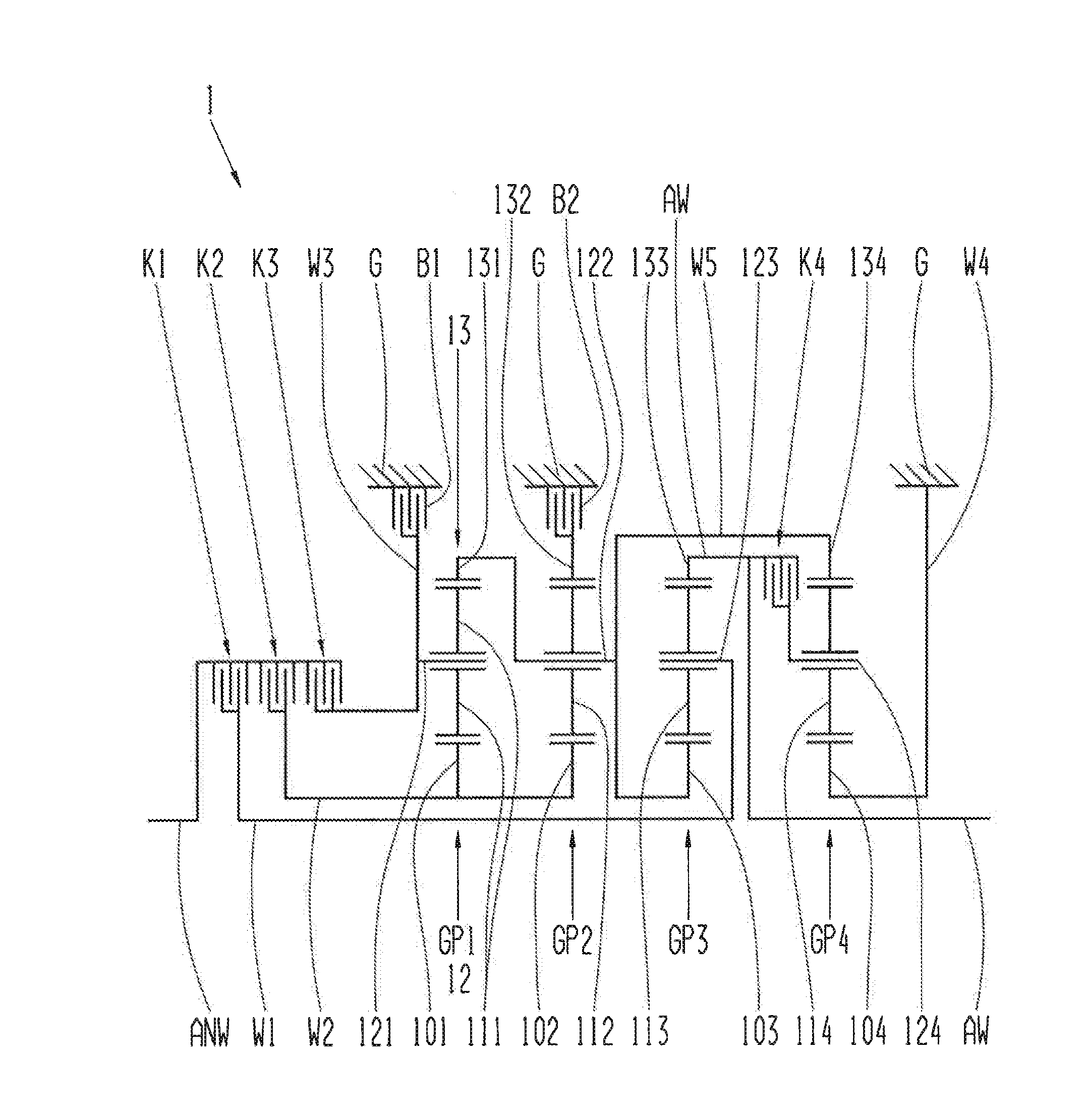
[0050]FIG. 1 shows a transmission in accordance with the present invention.

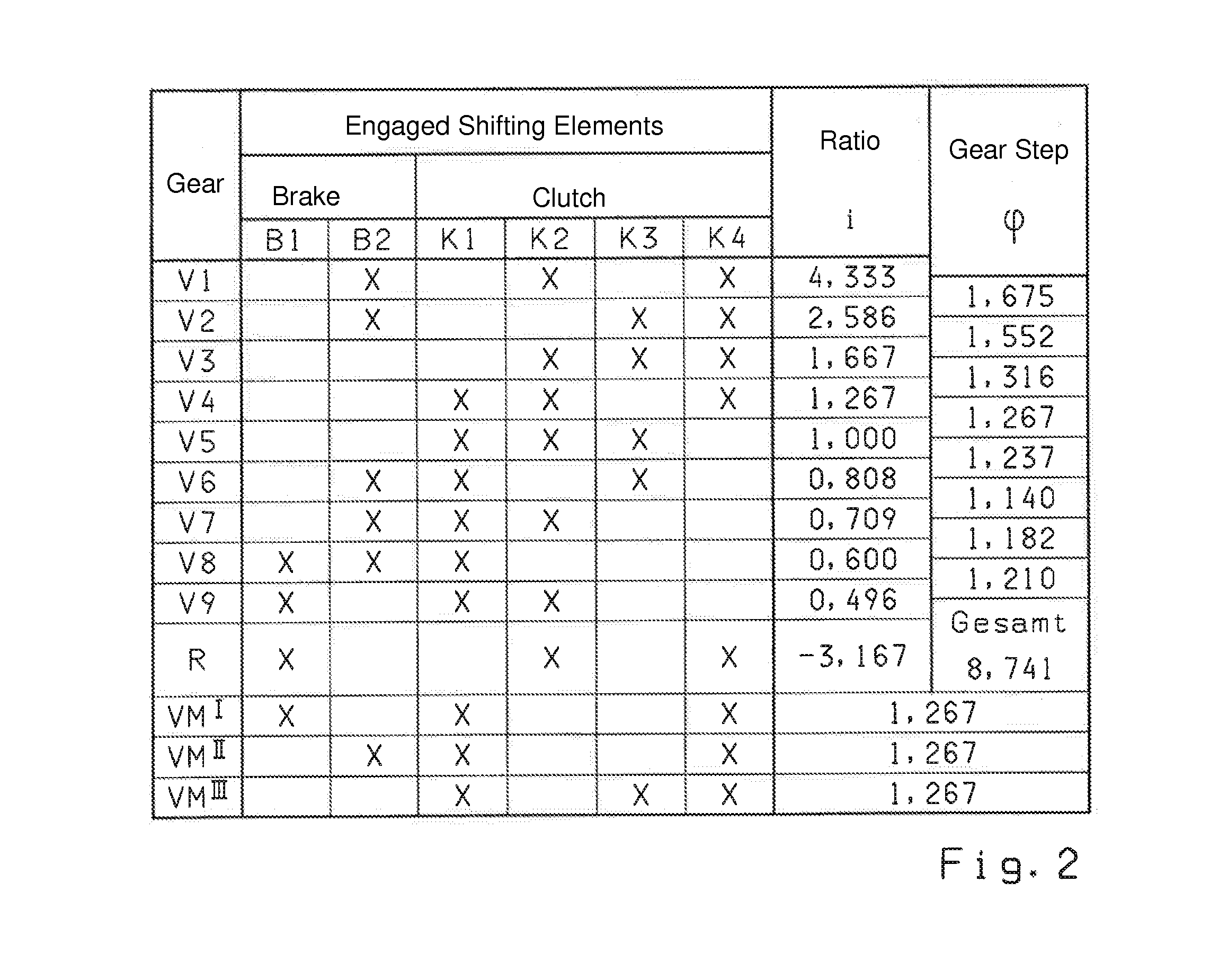
[0051]In FIG. 1, reference sign 1 designates a multi-speed transmission. The multi-stage transmission 1 features six shift elements in the form of four clutches K1, K2, K3, K4 and two brakes B1, B2. By means of the four clutches K1, K2, K3, K4, the drive side can be coupled or connected to the output side of the transmission for transferring power and torques through shafts and / or the planetary gear sets. For this purpose, the first clutch K1, the second clutch K2 and the third clutch K3 are connected to the drive shaft ANW on the drive side. The first clutch K1 is also connected to a first shaft W1, such that, when actuated, the first clutch K1 transfers power and torque from the drive shaft ANW to the first shaft W1. This correspondingly applies for the second clutch K2 and the third clutch K3. Upon locking the second clutch K2, power and torque are transferred from the drive shaft ANW to the second shaft W...

second embodiment

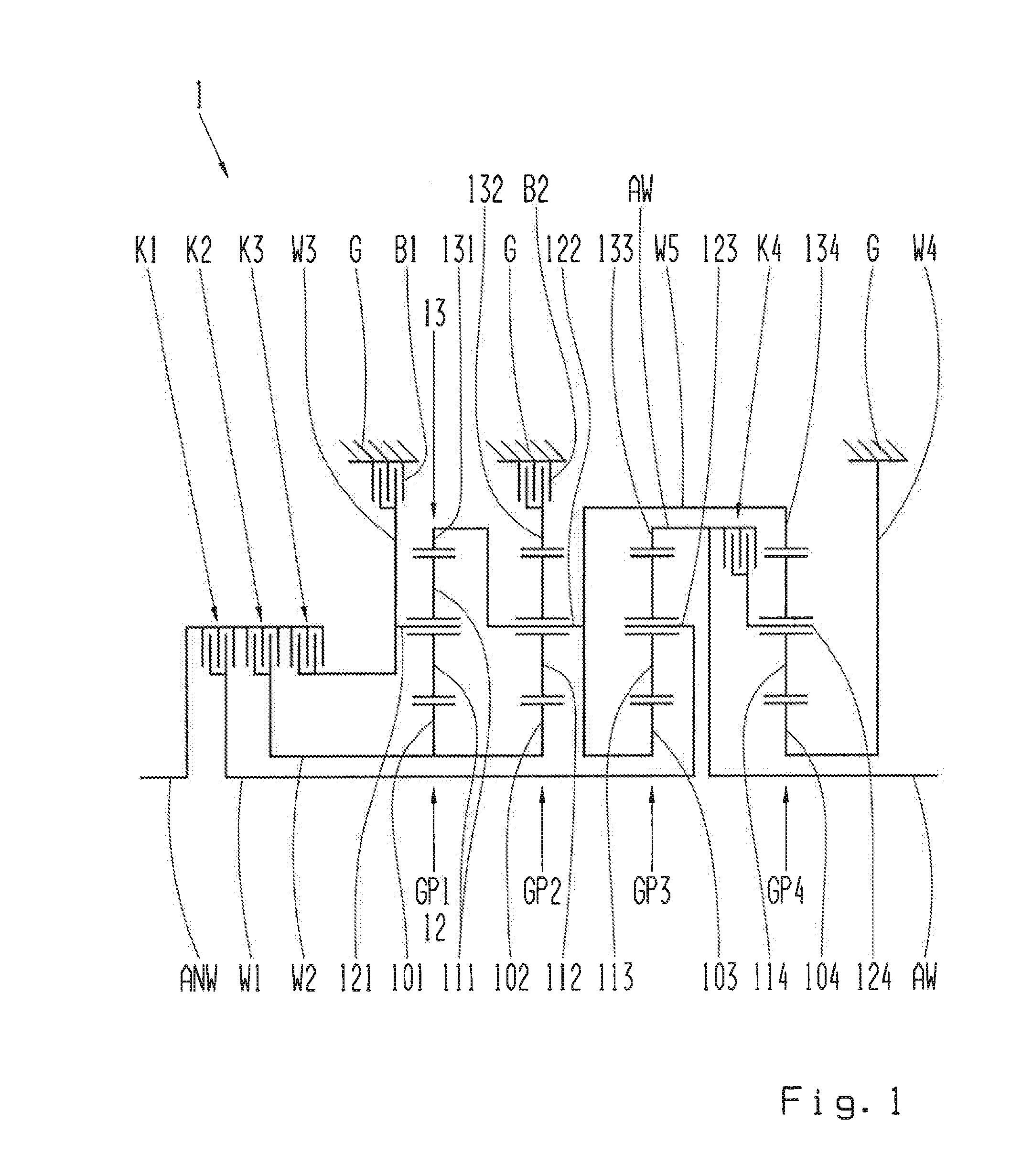
[0067]FIG. 3 shows a transmission in accordance with the present invention.

[0068]FIG. 3 essentially shows a transmission 1 in accordance with FIG. 1. In contrast to the transmission 1 in accordance with FIG. 1, the first planetary gear set GP1 is formed as a Ravigneaux planetary gear set. Therefore, the first planetary gear set GP1 features two planets 111a, 111b, which are rotatably mounted together on the bar 121 of the first planetary gear set and GP1 and mesh into each other. Furthermore, in contrast to the transmission 1 in accordance with FIG. 1, the third shaft W3, instead of the bar 121 of the first planetary gear set GP1, is now connected to the ring gear 131 of the first planetary gear set GP1. As in FIG. 1, the third shaft W3 is [connected], on the one hand, to the clutch K3 at the drive shaft ANW and, on the other hand, through the brake B1 to the housing G. The fifth shaft W5 for the transmission 1 in accordance with FIG. 3, in contrast to the transmission 1 in accordan...

third embodiment

[0069]FIG. 4 shows a transmission in accordance with the present invention.

[0070]FIG. 4 shows a transmission 1 in accordance with FIG. 1. In FIG. 4, two alternative positions A, B for the first clutch K1 can be viewed, with which the first clutch K1 can be arranged in a manner effectively equal to the position in accordance with FIG. 1.

[0071]The first alternative position A for the first clutch K1 is located between the ring gear of the third planetary gear set GP3 and the section of the output shaft AW that is connected to the fourth clutch K4.

[0072]The second alternative position B for the first clutch K1 is located between the sun gear 103 of the third planetary gear set GP3 and the section of the fifth shaft W5 that connects the ring gear 131 of the first planetary gear set GP1, the bar 122 of the second planetary gear set GP3 and the ring gear 134 of the fourth planetary gear set GP4 with each other.


PUM


Abstract

A multi-speed transmission is provided for a motor vehicle and includes a housing, a drive shaft, an output shaft, at least four planetary gear sets, whereas each of the planetary gear sets comprises one sun gear, at least one planet, one planetary carrier and one ring gear. The transmission includes several shift elements in the form of at least four clutches and at least two brakes. The drive shaft is connectable through the second clutch to the sun gear of the first and second planetary gear sets. The sun gear of the fourth planetary gear set is connected to the housing. The ring gear of the fourth planetary gear set is connectable to the planetary carrier of the second planetary gear set. The planetary carrier of the fourth planetary gear set is connectable through the fourth clutch to the output shaft. The ring gear of the second planetary gear set is connected through the second brake to the housing. The drive shaft is connectable through the third clutch to the first brake. The first brake is connected to the housing. The invention also relates to a method for operating the transmission along with a motor vehicle with the transmission.

Description

FIELD OF THE INVENTION[0001]The invention relates to a transmission, in particular a multi-speed transmission for a motor vehicle, including a housing, a drive shaft, an output shaft, at least four planetary gear sets, whereas each of the planetary gear sets comprises one sun gear, at least one planet, one planetary carrier and one ring gear. The transmission includes several shift elements in the form of at least four clutches and at least two brakes.BACKGROUND[0002]Such transmissions are known, for example, from WO 2012 / 052284 A1. In WO 2012 / 052284 A1, a multi-speed transmission with six forward gears and one reverse gear is shown, which comprises four planetary gear sets, seven rotatable shafts and five shift elements. The sun gear of the first planetary gear set is connected to the sixth shaft, which is attachable through a first brake to the housing of the transmission. The bar of the first planetary gear set is connected to the fifth shaft, which is connected to the sun gear o...

Claims


Application Information

Patent Timeline
Patent Type & Authority Applications(United States)
IPC IPC(8): F16H3/66
CPCF16H3/66F16H2003/445F16H2200/2097F16H2200/2012F16H2200/2046F16H2200/0065F16H3/666
Inventor BECK, STEFANSIBLA, CHRISTIANRIEGER, WOLFGANG
Owner ZF FRIEDRICHSHAFEN AG
Why Eureka
Try Eureka