

Recessed Light Apparatus
- Summary
- Abstract
- Description
- Claims
- Application Information
AI Technical Summary
Benefits of technology
Problems solved by technology
Method used
Image

Examples
Embodiment Construction
[0048]The following description is disclosed to enable any person skilled in the art to make and use the present invention. Preferred embodiments are provided in the following description only as examples and modifications will be apparent to those skilled in the art. The general principles defined in the following description would be applied to other embodiments, alternatives, modifications, equivalents, and applications without departing from the spirit and scope of the present invention.
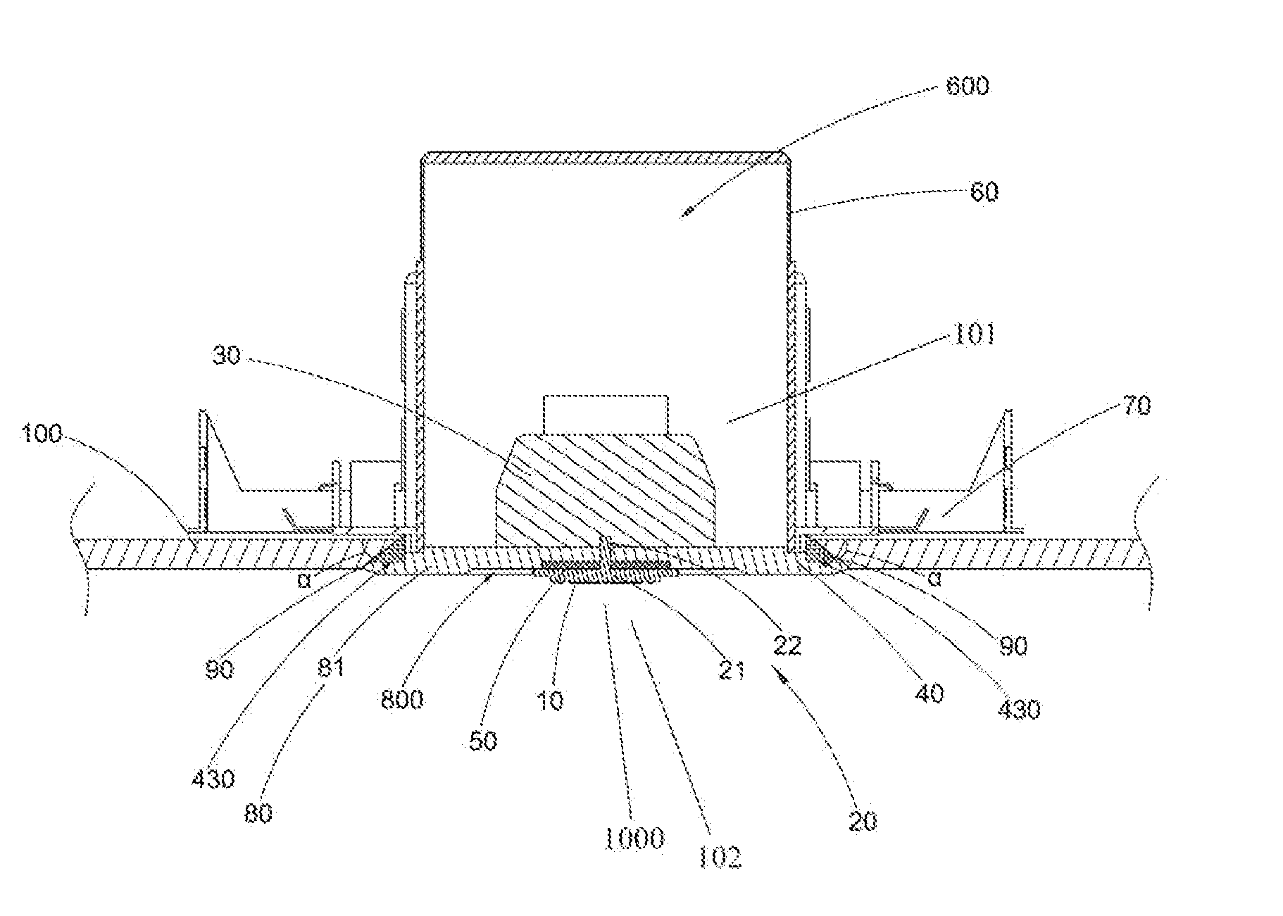
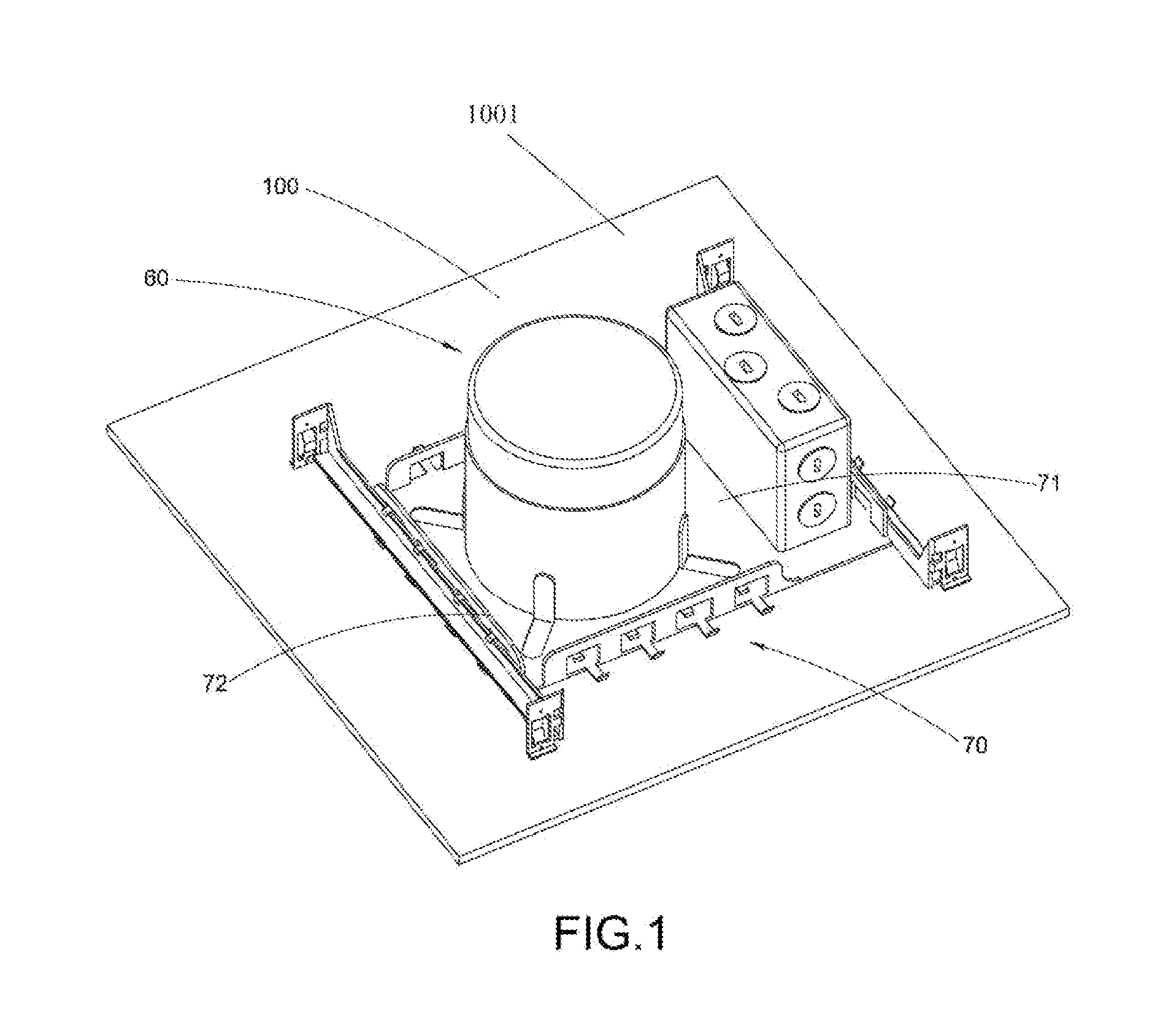
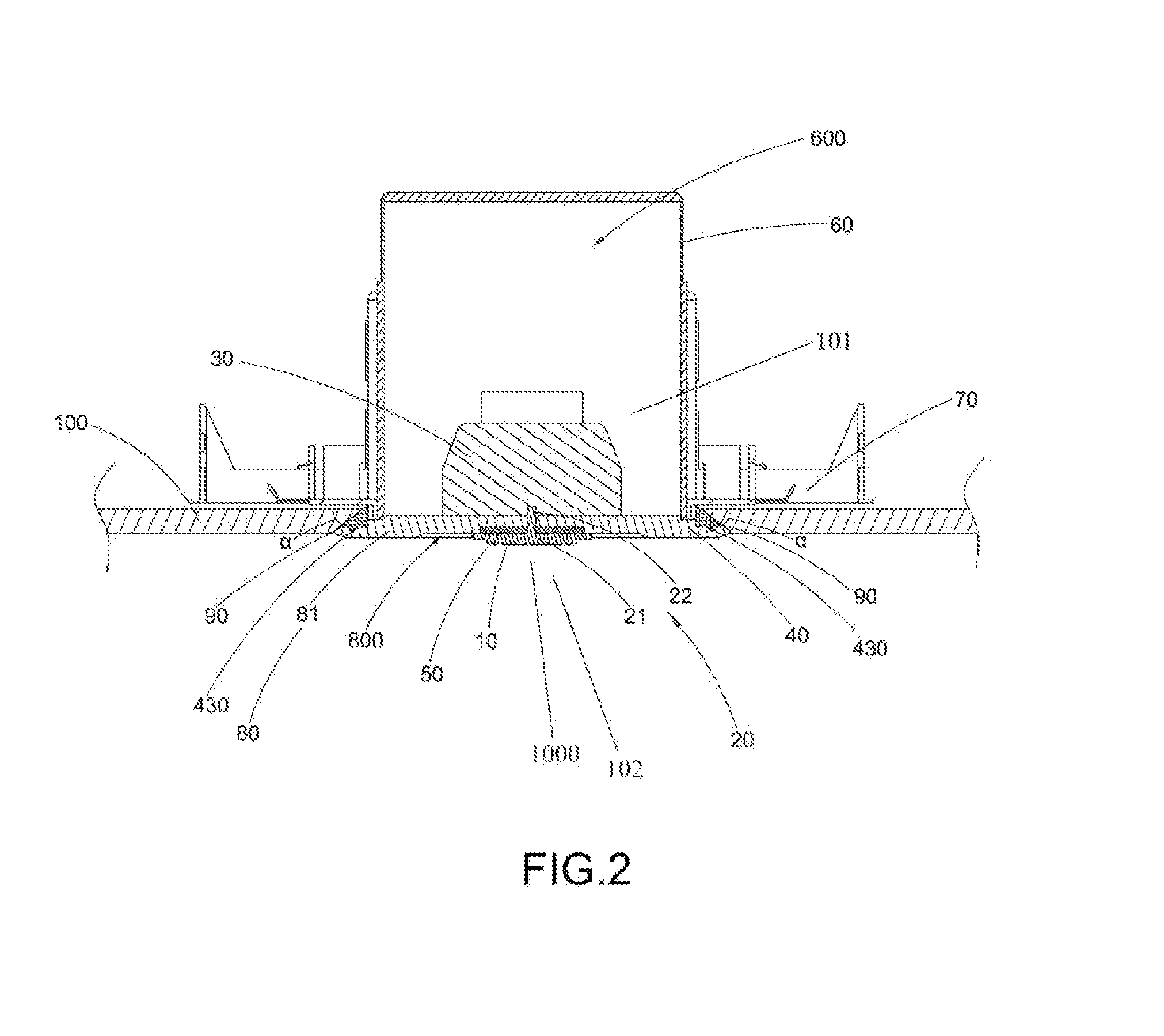
[0049]Referring to FIGS. 1 to 5B of the drawings, a recessed light apparatus according to a first preferred embodiment of the present invention is illustrated, wherein the ceiling light apparatus, such as a recessed light apparatus, comprises a light source unit 10, at least a heat conductive element 20, and at least a heat sink 30. The light source unit 10 is arranged for electrically connected to an external power source for operation. The heat conductive element 20 is extended from the light s...
PUM
 Abstract
Description
Claims
Application Information