Packed rock bed thermal energy storage facility

a thermal energy storage and rock bed technology, applied in the direction of regenerative heat exchangers, indirect heat exchangers, lighting and heating apparatus, etc., can solve the problems of inability to meet the needs of use, lack of use, and existing proposals for packing rock bed storage facilities that are relatively costly or impractical, and achieve the effect of increasing costs

Inactive Publication Date: 2016-03-24
STELLENBOSCH UNIVERSITY
View PDF7 Cites 6 Cited by
  • Summary
  • Abstract
  • Description
  • Claims
  • Application Information

AI Technical Summary

Benefits of technology

[0012]The facility could cover an area as small as a few square metres, or several thousand square metres or more. When the size is such that further scaling-up increases the cost non-linearly due to the requirements of the containme

Problems solved by technology

The use of packed rock beds has, on the other hand, received considerable attention from a theoretical point of view but, as far as applicant is aware, has not been implemented to any appreciable extent at high temperatures in practice although it is understoo

Method used


Image

  • Packed rock bed thermal energy storage facility
  • Packed rock bed thermal energy storage facility
  • Packed rock bed thermal energy storage facility

Examples


Embodiment Construction

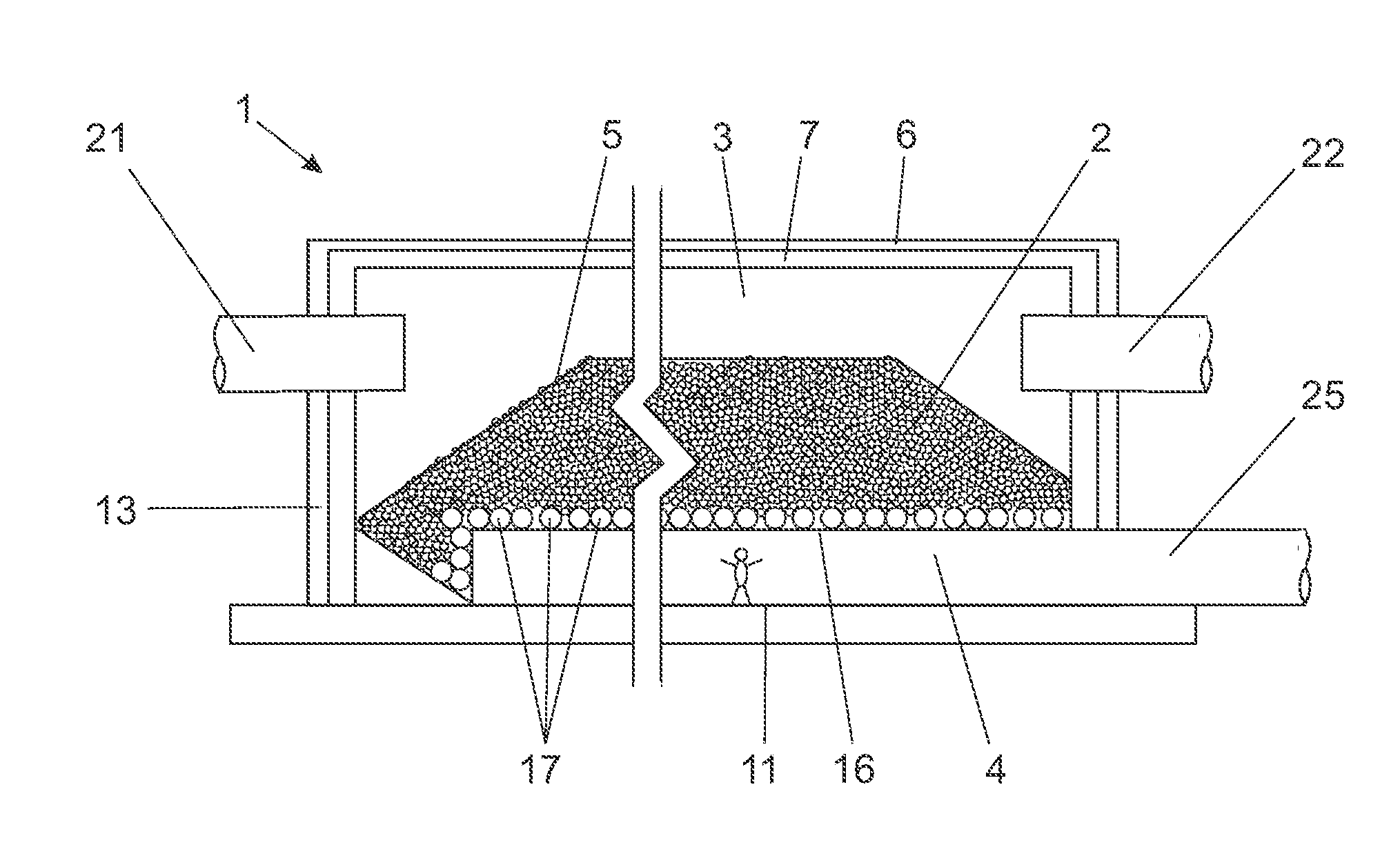
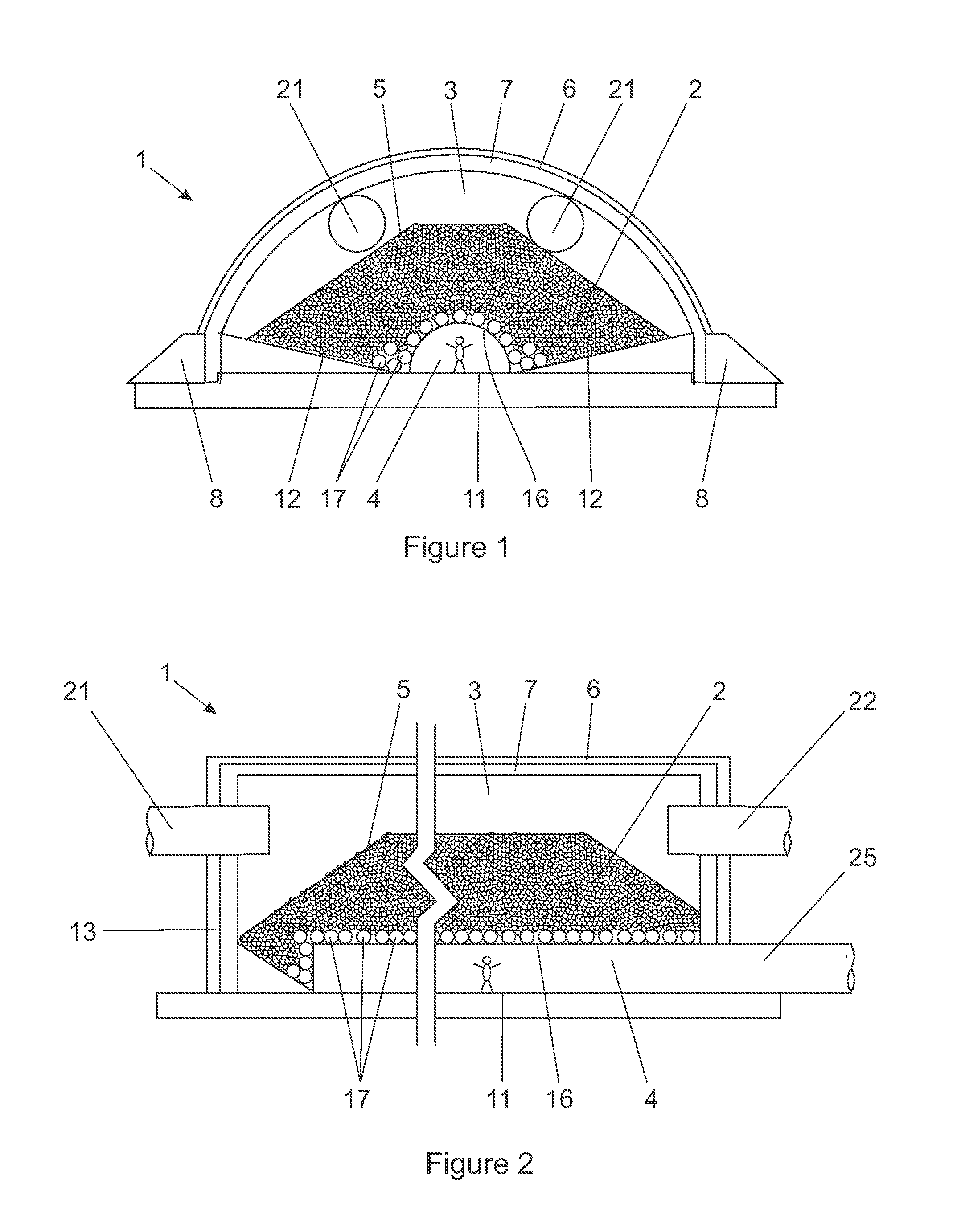
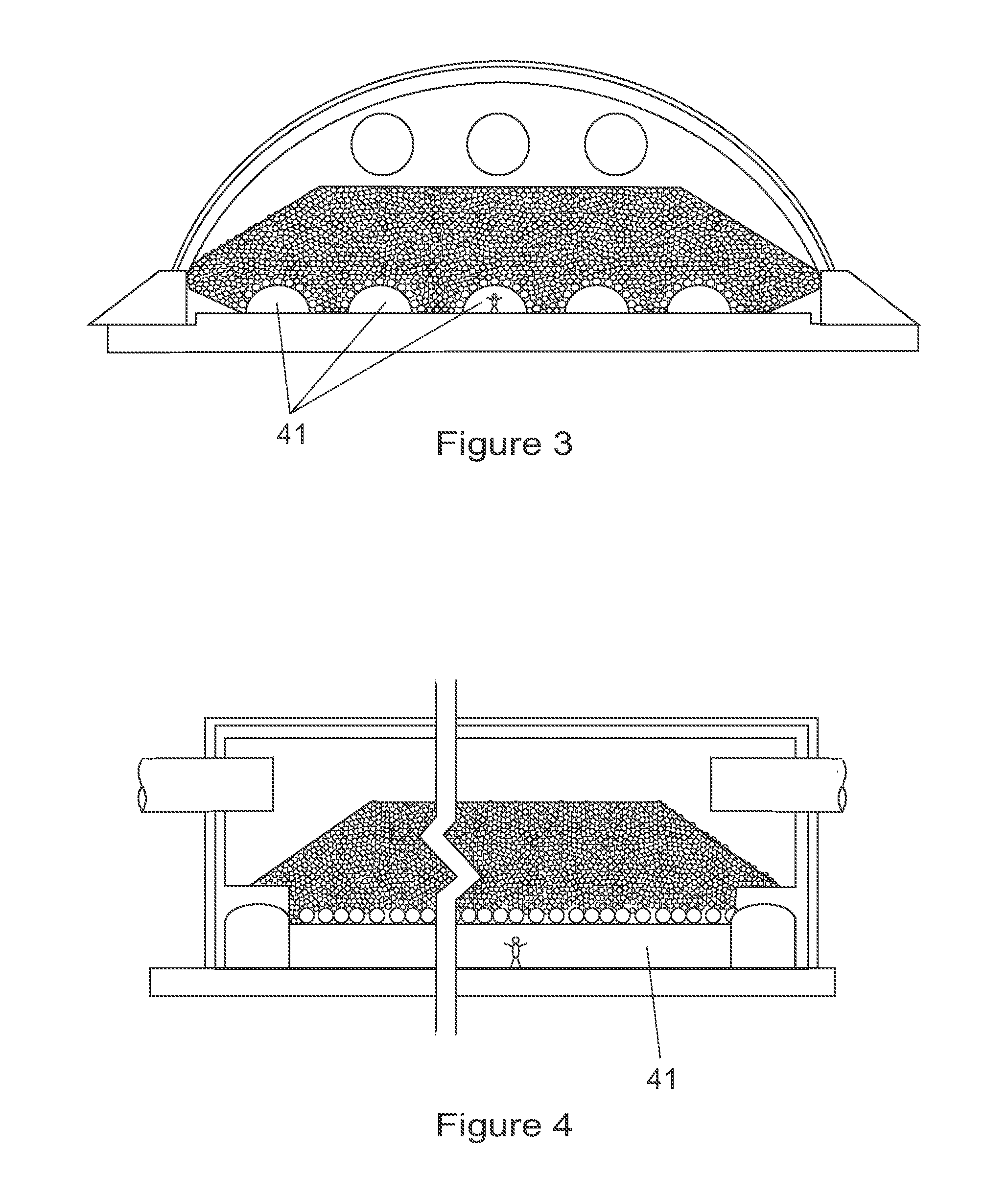
[0023]Referring now to the drawings, one embodiment of packed rock bed thermal energy storage facility (1) comprises a pile (2) of individual rock units and first and second spaces, (3) and (4) respectively, separated by the rock bed such that working fluid may flow between the first and second spaces by way of interstices between rock units forming the rock bed. In so doing, heat may be either transferred from the working fluid to the rock bed in order to store heat in the rock bed or can be transferred from the rock bed to a working fluid to recover heat stored in the rock bed by absorbing it into the working fluid, as the case may be.

[0024]The first space (3) is formed between an upper surface (5) of the pile of rocks and an arched roof (6) of an enclosure spaced upwardly from the upper surface of the pile. The entire upper surface of the pile is thus exposed to the first space. In this embodiment of the invention, the rock pile has a flat top and surrounding sides and an end tha...


PUM


Abstract

A packed rock bed thermal energy storage facility is provided in the form of a pile of unconstrained rock that is free to expand and contract with changing temperature without creating significant stress. A hot fluid inlet and outlet space is provided above the bed and a cold fluid inlet and outlet space is formed by a grid and larger rocks, or by larger rocks only, that support the pile toward a bottom of the bed. Fluid flow can occur downward through the rock bed during heating of the bed and upward through the rock bed during cooling of the bed in a heat recovery cycle. The bed is completely covered by an insulated arched roof. The rock bed may be an enclosure having a roof, walls and a floor with a lower central region and somewhat inclined side regions extending at a gentle slope towards sidewalls supporting the roof.

Description

FIELD OF THE INVENTION[0001]This invention relates to a packed rock bed thermal storage facility for use in the storage of thermal energy that has been derived from some suitable source.BACKGROUND TO THE INVENTION[0002]The generation of power from sources using conventional fossil fuels is increasingly being replaced by the use of renewable energy of one or other type. As far as the present patent application is concerned, the invention is especially appropriate for use in association with concentrating solar power plants or combined cycle power plants, although it is not limited to these applications.[0003]The use of solar energy is associated with the need for storing the solar energy collected for use at a later time so that energy is available at night time or when the sun is obscured, typically by cloud. One practical way of storing energy is in the form of heat (thermal energy) that can be used subsequently for the generation of electricity, by way of a steam generating cycle ...

Claims


Application Information

Patent Timeline
IPC IPC(8): F28D20/00
CPCF28D20/0056F28D2020/0078F28D2020/0021F28D20/00F28D2020/0069Y02E20/16Y02E60/14
Inventor KROGER, DETLEV, GUSTAV
Owner STELLENBOSCH UNIVERSITY
Why Eureka
Try Eureka