Image measurement device
- Summary
- Abstract
- Description
- Claims
- Application Information
AI Technical Summary
Benefits of technology
Problems solved by technology
Method used
Image

Examples
first embodiment
[0023]Embodiments of an image measurement technique according to the invention will be described below with reference to drawings.
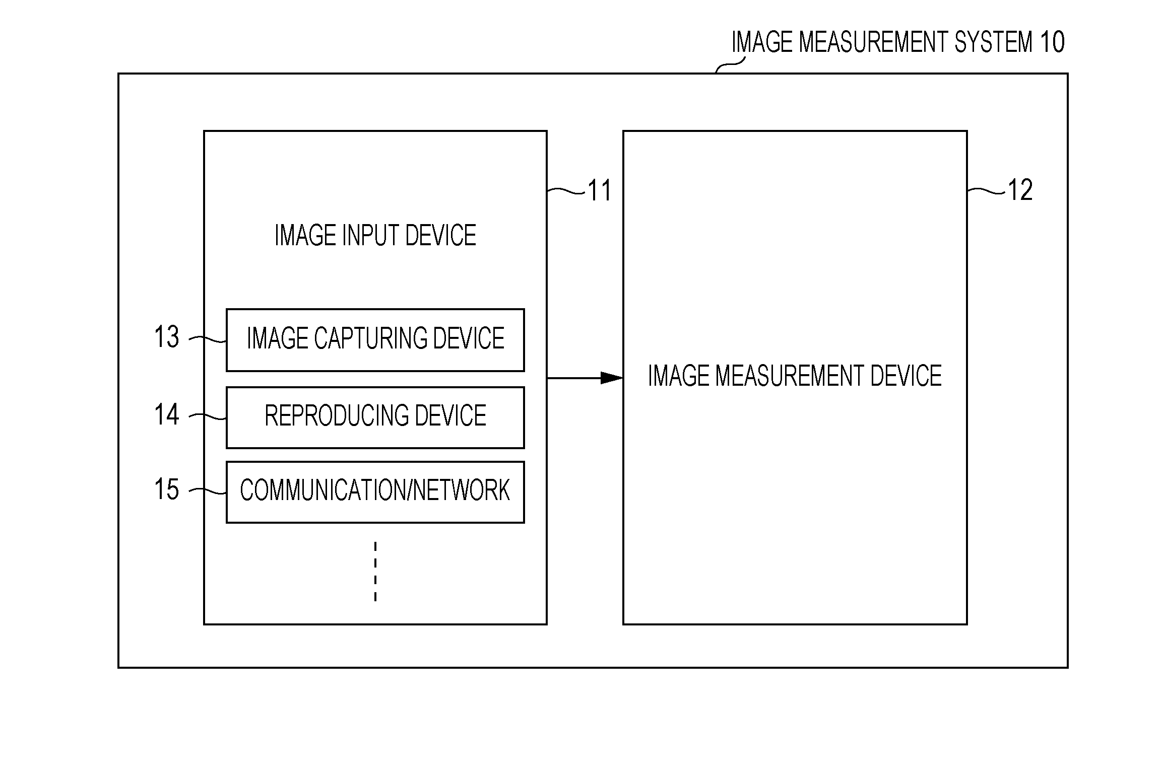
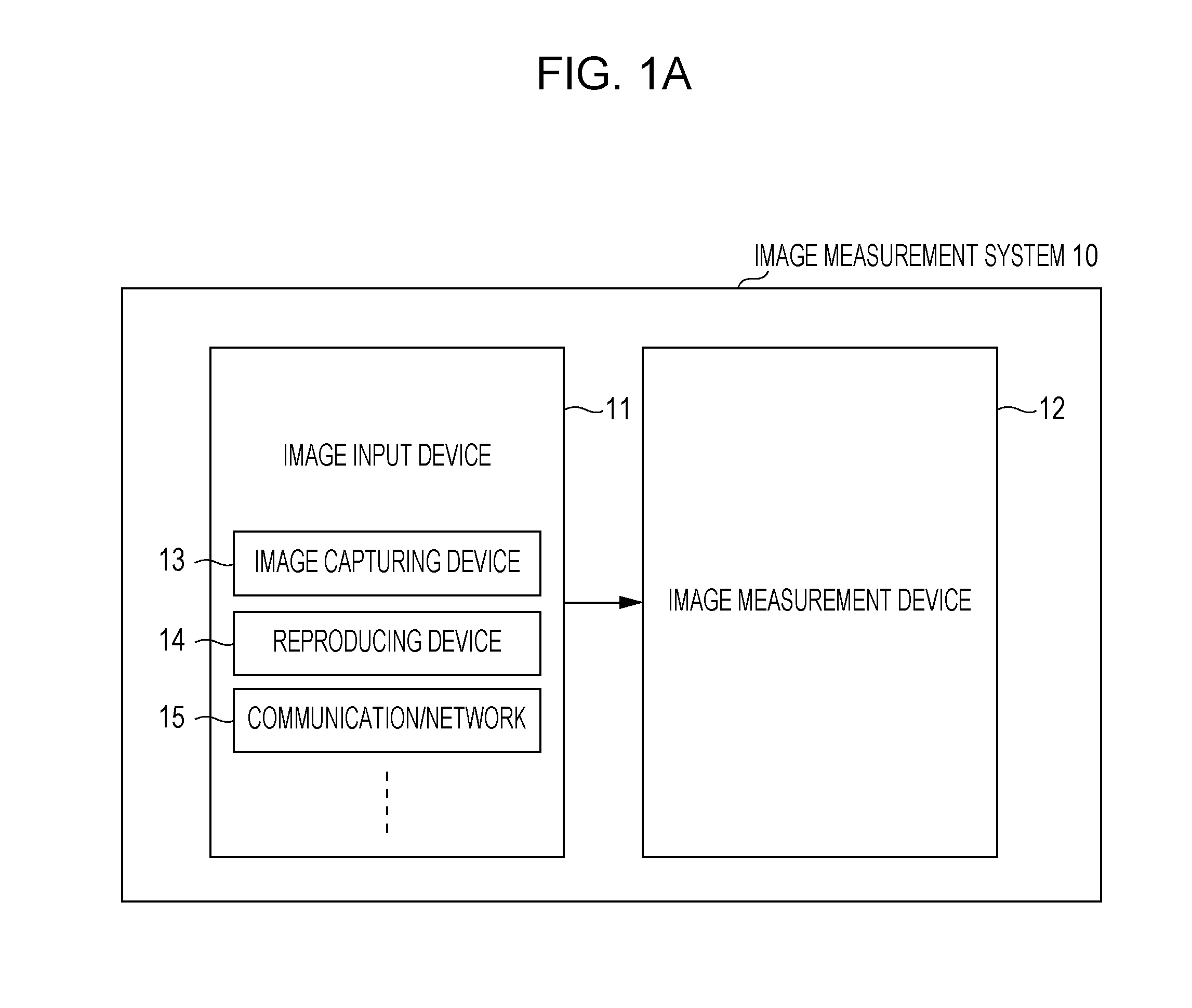
[0024]FIG. 1A is a functional block diagram illustrating a schematic configuration example of an image measurement system provided with an image measurement device in an embodiment of the invention. An image measurement system 10 has an image input device 11 and an image measurement device 12. The image input device 11 is, for example, an image capturing device 13, a reproducing device 14, a communication / network 15, or the like, acquires image data of an object that is a measurement target, and outputs the image data to the image measurement device 12. The image measurement device 12 computes a distance between two desired regions from image data which is input. In the present embodiment, description will be given by taking an image measurement system, which is composed of the image capturing device 13 and the image measurement device 12, as an example. ...
second embodiment
[0086]An image measurement device according to a second embodiment of the invention will be described. The second embodiment is a device capable of measuring distance to a plane region easily, and by following a measurement target which is designated in a first measurement region and measuring a distance to a plane which is designated as a second measurement region chronologically, change in a distance (height) between an object which is moving on the plane and the plane is able to be measured.
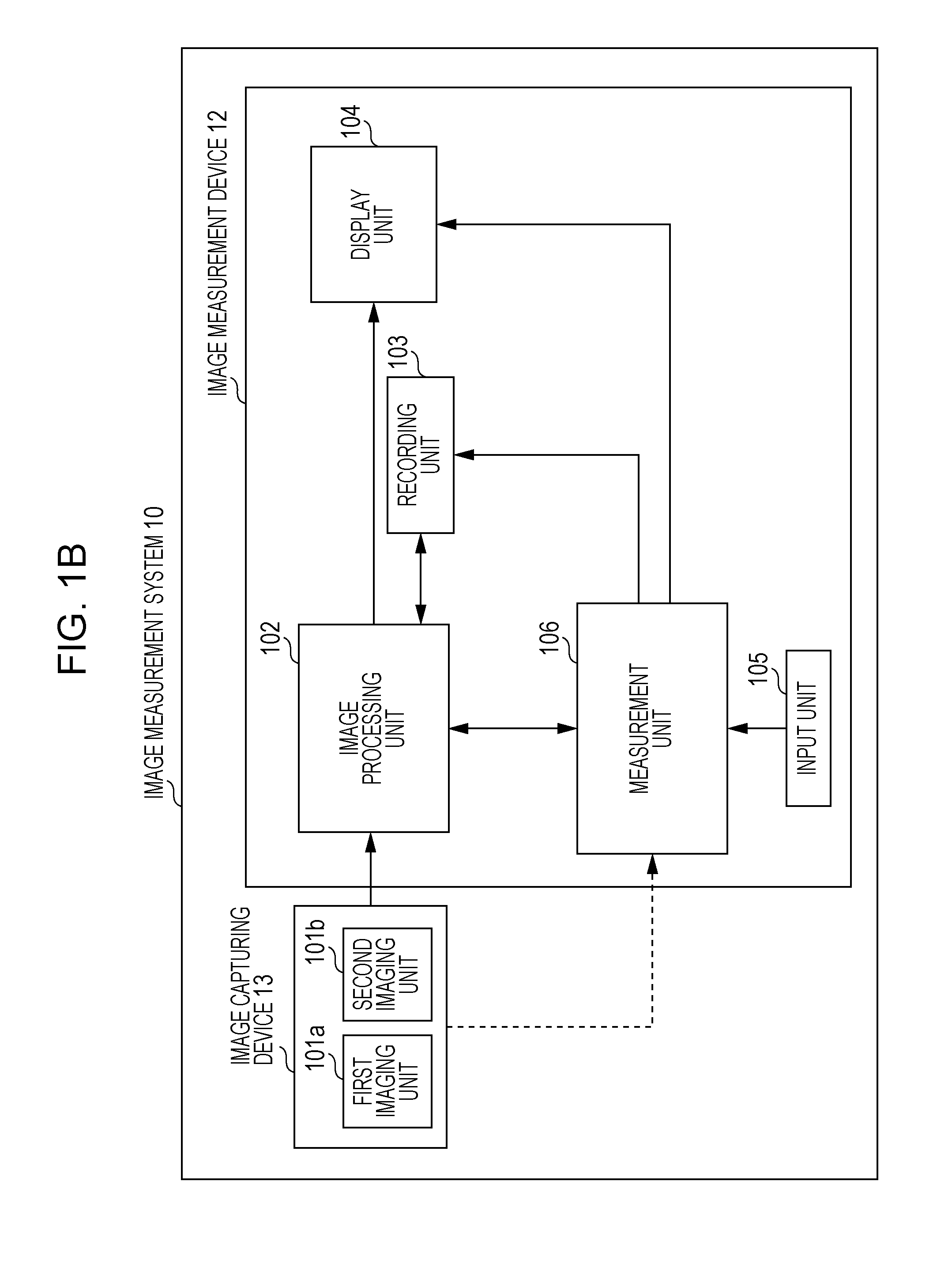
[0087]A configuration of an image capturing device in the second embodiment is almost similar to the configuration illustrated in FIG. 1, and the image capturing device 13 has the imaging unit 101, the image processing unit 102, the recording unit 103, the display unit 104, the input unit 105, and the measurement unit 106. Detailed description of each unit is similar and therefore omitted. Next, a configuration of the measurement unit 106 is illustrated in FIG. 7. The measurement unit 106 in t...
third embodiment
[0109]In the present embodiments 1 and 2, when the distance information acquisition unit 114 acquires distance information, the distance information is computed from images having disparity, but means is not limited thereto as long as obtaining distance information corresponding to a photographed image region. For example, data indicating one photographed image and distance information in a real space for each region of the photographed image may be input. One example of the data indicating distance information includes a distance image indicating a relative value of distances of each pixel in a real space. In this case, the distance information acquisition unit 114 extracts distance information corresponding to a measurement region extracted from the distance image from the distance image data to output as the distance information. The distance computation unit 117 uses the acquired distance information and a parameter for converting it into a distance in a real space to convert in...
PUM
 Abstract
Description
Claims
Application Information
 - Generate Ideas
- Intellectual Property
- Life Sciences
- Materials
- Tech Scout
- Unparalleled Data Quality
- Higher Quality Content
- 60% Fewer Hallucinations
Browse by: Latest US Patents, China's latest patents, Technical Efficacy Thesaurus, Application Domain, Technology Topic, Popular Technical Reports.
© 2025 PatSnap. All rights reserved.Legal|Privacy policy|Modern Slavery Act Transparency Statement|Sitemap|About US| Contact US: help@patsnap.com