Antenna, antenna device, and wireless device

a wireless device and antenna technology, applied in the direction of antennas, antennas earthing switches, antenna feed intermediates, etc., can solve the problem of difficult control of the directivity of the antenna

Active Publication Date: 2016-03-24
ASAHI GLASS CO LTD
View PDF4 Cites 25 Cited by
  • Summary
  • Abstract
  • Description
  • Claims
  • Application Information

AI Technical Summary

Benefits of technology

[0010]According to one aspect of the present invention, an antenna, an antenna device, and a wireless device are provided that include a feeding element that is connected to a feeding point; a first radiating element that is spaced apart from the feeding element and is fed by being coupled to the feeding element through electromagnetic field coupling to function as a radiating conductor; a second radiating element that is spaced apart from the feeding element and is fed by being coupled to the feeding element through electromagnetic field coupling to function as a radiating conductor; a first control element that is connected to the feeding element via a first impedance variable unit and is arranged such that when an impedance of the first impedance variable unit at a resonant frequency of the first radiating element is decreased, the electromagnetic field coupling between the feeding element and the first radiating element is weakened and the function of the first radiating element as the radiating conductor is degraded; a second control element that is connected to the feeding element via a second impedance variable unit and is arranged such that when an impedance of the second impedance variable unit at a resonant frequency of the second radiating element is decreased, the electromagnetic field coupling between the feeding element and the second radiating element is weakened and the function of the second radiating element as the radiating conductor is degraded; and a control unit that controls the first impedance variable unit to adjust the connection between the feeding element and the first control element, and controls the second impedance variable unit to adjust the connection between the feeding element and the second control element.
[0011]According to another aspect of the present invention, an antenna, an antenna device, and a wireless device are provided that include a feeding element that is connected to a feeding point; a first radiating element that is spaced apart from the feeding element and is fed by being coupled to the feeding element through electromagnetic field coupling to function as a radiating element; a second radiating element that is spaced apart from the feeding element and is fed by being coupled to the feeding element through electromagnetic field coupling to function as a radiating element; a first control element that is connected to the feeding element via a first impedance variable unit; a second control element that is connected to the feeding element via a second impedance variable unit; and a control unit that controls the first impedance variable unit to adjust the connection between the feeding element and the first control element, and controls the second impedance variable unit to adjust the connection between the feeding element and the second control element. The first control element is arranged such that a high impedance portion of the first control element having a high impedance at a resonant frequency of the first radiating element and a low impedance portion of the first radiating element having a low impedance at the resonant frequency of the first radiating element are positioned close to each other, and the second control element is arranged such that a high impedance portion of the second control element having a high impedance at a resonant frequency of the second radiating element and a low impedance portion of the second radiating element having a low impedance at the resonant frequency of the second radiating element are positioned close to each other.

Problems solved by technology

However, it has been difficult to control the directivity of an antenna that has a contactless feeding system as disclosed in Patent Document 2 where a feeding element connected to a feeding point is coupled to a radiating element (parasitic element) without being in contact.
For example, the switching technique disclosed in Patent Document 1 that involves controlling the directivity of an antenna by switching the connection point of a feeding element to a radiating element cannot be implemented in the antenna disclosed in Patent Document 2 because the feeding element and the radiating element have to be coupled without being in contact.

Method used


Image

  • Antenna, antenna device, and wireless device
  • Antenna, antenna device, and wireless device
  • Antenna, antenna device, and wireless device

Examples


first embodiment

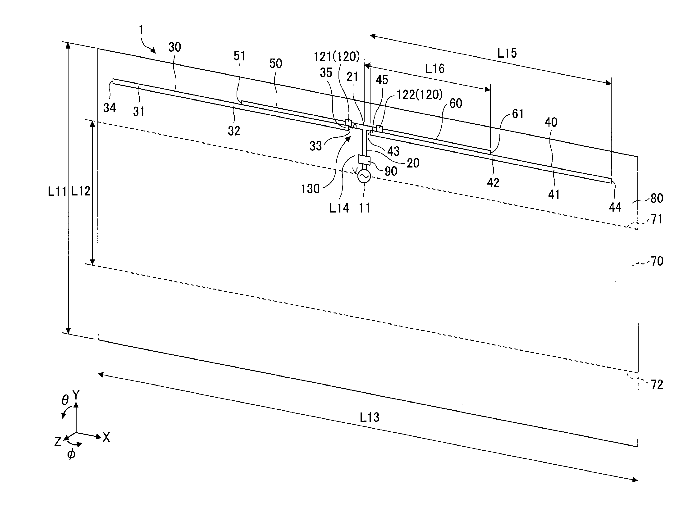
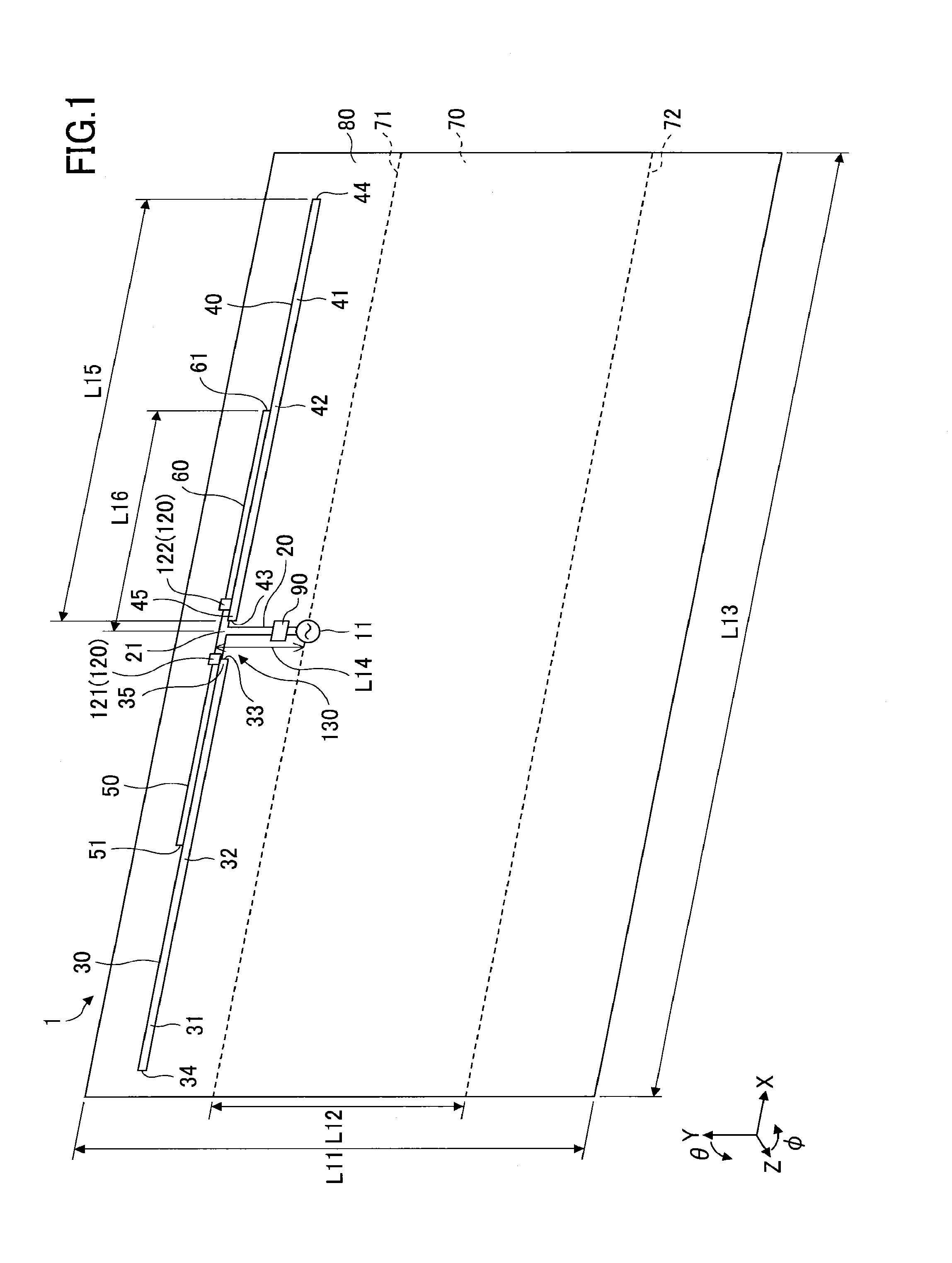
[0046]FIG. 1 is a perspective view of an exemplary computer simulation model for analyzing the operation of an antenna 1 according to the present invention. Note that in the present example, CST Microwave Studio (registered trademark) by Computer Simulation Technology AG (CST) was used as an electromagnetic field simulator.

[0047]The antenna 1 includes a feeding point 11, a ground plane 70, a feeding element 20, a first radiating element 30, a second radiating element 40, a first feeding portion 35, a second feeding portion 45, a first control element 50, a second control element 60, and an impedance control unit 120. Note that in the following descriptions, the first radiating element 30, the second radiating element 40, the first feeding portion 35, the second feeding portion 45, the first control element 50, and the second control element 60 may simply be referred to as “radiating element 30,”“radiating element 40,”“feeding portion 35,”“feeding portion 45,”“control element 50,” an...

second embodiment

[0139]FIG. 7 is a perspective view of a computer simulation model for analyzing the operation of an antenna device 201 including antennas 1 and 2 according to the present invention. Note that in the present example, CST Microwave Studio (registered trademark) by Computer Simulation Technology AG (CST) was used as an electromagnetic field simulator. Also, note that descriptions of features of the present embodiment that may be substantially identical to those of the embodiment described above may be simplified or omitted.

[0140]The antenna 2 of the antenna device 201 may have a configuration that is substantially identical to the configuration of the antenna 1, and is arranged on the opposite side of the antenna 1 with respect to the ground plane 70. The antenna 2 includes a feeding element 22, a radiating element 36, a radiating element 46, a control element 52, a control element 62, an impedance control unit 125, and a matching circuit 91.

[0141]The feeding element 22 is a conductor ...

third embodiment

[0147]FIG. 8 is a perspective view of a computer simulation model for analyzing the operation of an antenna 3 according to the present invention. Note that in the present example, CST Microwave Studio (registered trademark) by Computer Simulation Technology AG (CST) was used as an electromagnetic field simulator. Also, note that descriptions of features of the present embodiment that may be substantially identical to those of the embodiments described above may be simplified or omitted.

[0148]The antenna 3 includes a ground plane 70, a plate conductor 150, a feeding element 20, a radiating element 160, a radiating element 170, a control element 50, a control element 60, an impedance control unit 120, and optionally, a matching circuit 90. Note that the feeding element 20, the control element 50, the control element 60, the impedance control unit 120, and the matching circuit 90 may be substantially identical to those described above with reference to FIG. 1.

[0149]The ground plane 70 ...


PUM


Abstract

An antenna includes a feeding element connected to a feeding point, a first radiating element that is spaced apart from the feeding element and is coupled to the feeding element through electromagnetic field coupling, a second radiating element that is spaced apart from the feeding element and is coupled to the feeding element through electromagnetic field coupling, a first control element that is connected to the feeding element via a first impedance variable unit, and a second control element that is connected to the feeding element via a second impedance variable unit, and a control unit that controls the first impedance variable unit to adjust the connection between the feeding element and the first control element and controls the second impedance variable unit to adjust the connection between the feeding element and the second control element.

Description

CROSS-REFERENCE TO RELATED APPLICATION[0001]The present application is a continuation application filed under 35 U.S.C. 111(a) claiming benefit under 35 U.S.C. 120 and 365(c) of PCT International Application No. PCT / JP2014 / 066334 filed on Jun. 19, 2014 and designating the U.S., which claims priority to Japanese Patent Application No. 2013-131195 filed on Jun. 21, 2013. The entire contents of the foregoing applications are incorporated herein by reference.BACKGROUND OF THE INVENTION[0002]1. Field of the Invention[0003]The present invention generally relates to an antenna, an antenna device, and a wireless device such as a mobile phone.[0004]2. Description of the Related Art[0005]Techniques are known for controlling the directivity of an antenna by switching a connection destination of a feeding point. For example, Japanese Laid-Open Patent Publication No. 2012-186562 (Patent Document 1) discloses an antenna including a switch for switching the directivity of a radiating conductor by ...

Claims


Application Information

Patent Timeline
Patent Type & Authority Applications(United States)
IPC IPC(8): H01Q1/50H01Q9/06
CPCH01Q9/065H01Q1/50H01Q9/16H01Q9/285
Inventor SAYAMA, TOSHIKISONODA, RYUTAIKAWA, KOJI
Owner ASAHI GLASS CO LTD
Why Eureka
Try Eureka