Eureka AIR delivers breakthrough ideas for toughest innovation challenges, trusted by R&D personnel around the world.

Noise canceler for use in a transceiver

a transceiver and noise cancellation technology, applied in the direction of transmission, electrical equipment, etc., can solve the problems of reducing the sensitivity of the receiver, increasing the noise floor of the receiver, and relatively high insertion loss of the rx filter

Active Publication Date: 2016-03-24
QUALCOMM INC
View PDF6 Cites 52 Cited by
  • Summary
  • Abstract
  • Description
  • Claims
  • Application Information

AI Technical Summary

Benefits of technology

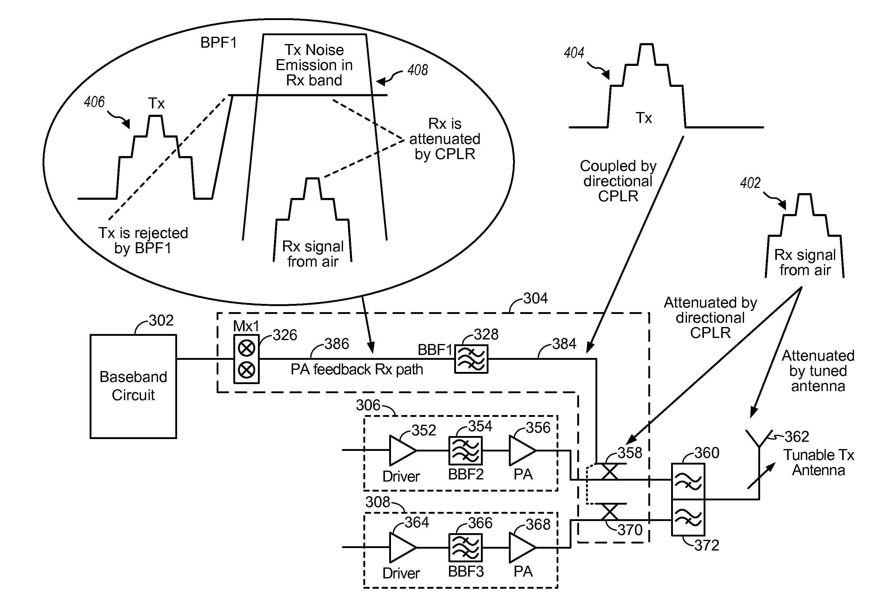
The patent text describes a problem in wireless communication systems where signals transmitted by a transceiver device may leak into the receiver's path, causing increased noise floor and reduced sensitivity. The conventional solution of using filters for both the transmit and receive paths results in a significant noise floor penalty in the receive path and higher gain and power consumption in the transmit path. The patent proposes a noise canceler to reduce the amount of Tx noise leaking into the Rx path while overcoming these problems. The technical effect of the patent is to provide a solution to reduce the noise floor and improve the sensitivity of wireless devices.

Problems solved by technology

Reception of transmit signals increases the receiver's noise floor and therefore reduces the receiver's sensitivity.
The Rx filter has relatively high insertion loss to support sharp rejection thus increasing the Rx noise floor.
As a result, conventional solutions to address the problems of out-of-band Tx noise leaking into the Rx path utilize filters for both the Tx and Rx paths which result in a significant noise floor penalty in the Rx path and higher gain and power at the Tx path, resulting in increased power consumption, and high parts count.

Method used


Image

  • Noise canceler for use in a transceiver
  • Noise canceler for use in a transceiver
  • Noise canceler for use in a transceiver

Examples


Embodiment Construction

[0019]The detailed description set forth below is intended as a description of exemplary designs of the present disclosure and is not intended to represent the only designs in which the present disclosure can be practiced. The term “exemplary” is used herein to mean “serving as an example, instance, or illustration.” Any design described herein as “exemplary” is not necessarily to be construed as preferred or advantageous over other designs. The detailed description includes specific details for the purpose of providing a thorough understanding of the exemplary designs of the present disclosure. It will be apparent to those skilled in the art that the exemplary designs described herein may be practiced without these specific details. In some instances, well-known structures and devices are shown in block diagram form order to avoid obscuring the novelty of the exemplary designs presented herein.

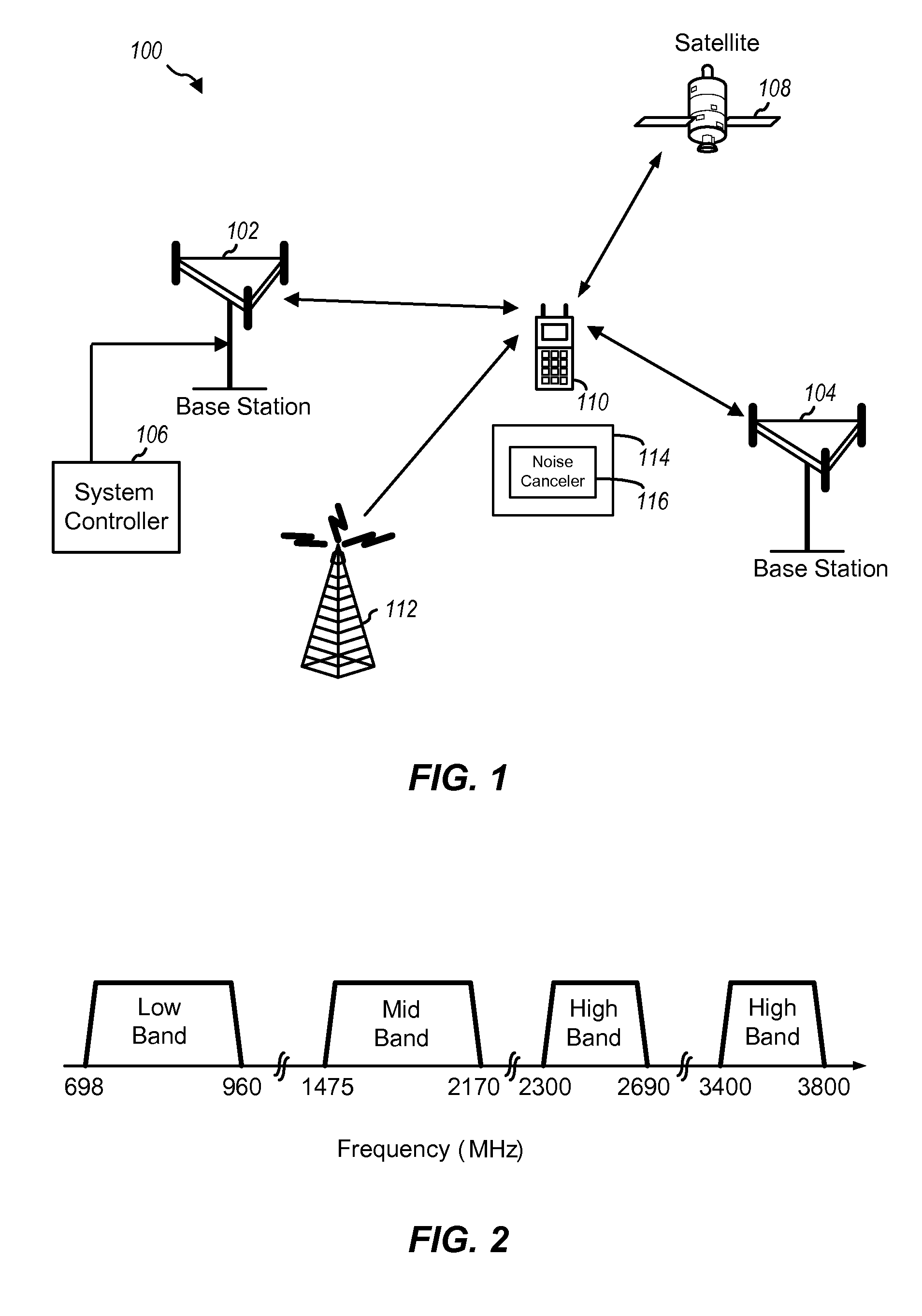
[0020]FIG. 1 shows a wireless device 110 communicating in a wireless communication system...


PUM


Abstract

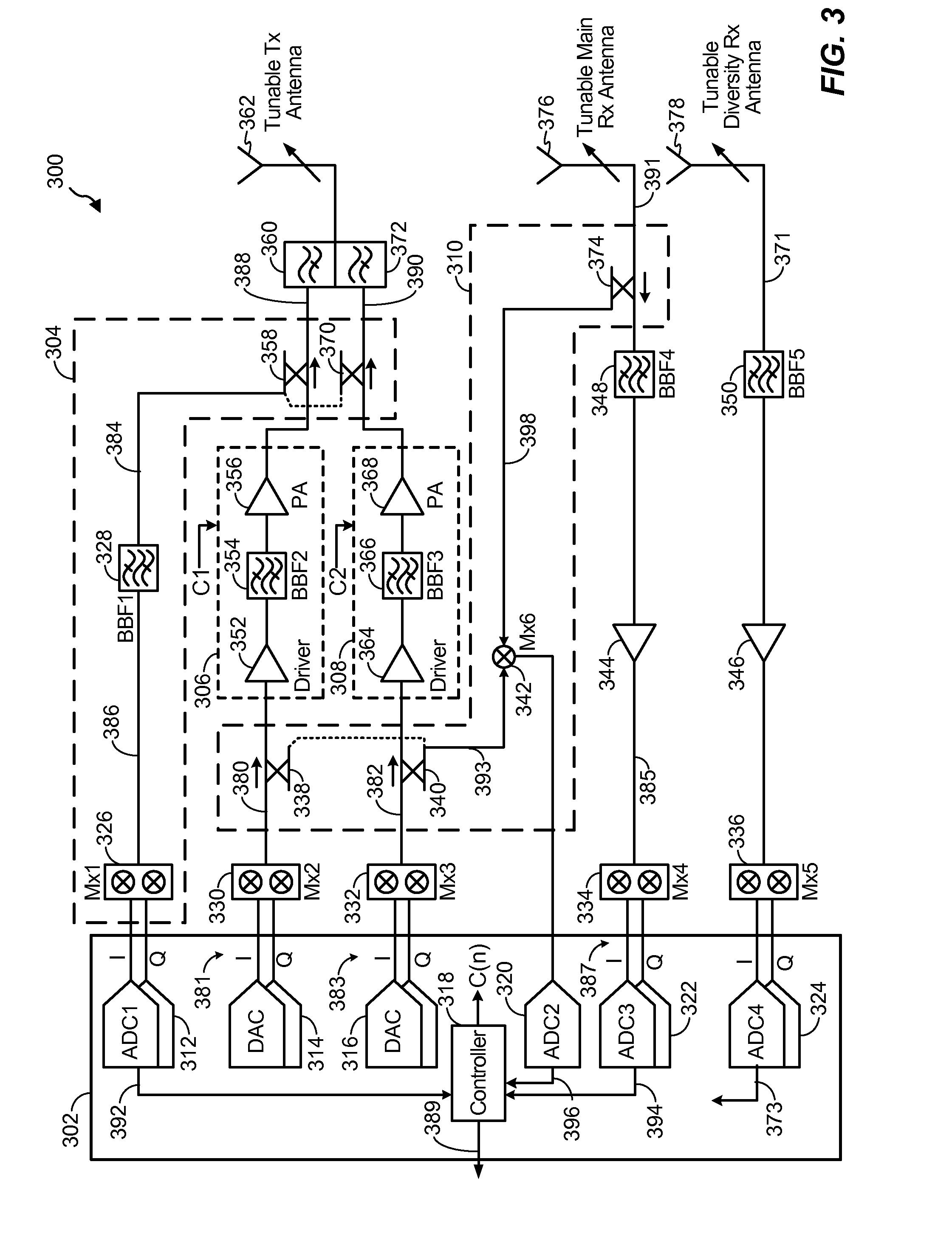
A noise canceler for use in a transceiver is disclosed. In an exemplary embodiment, an apparatus includes a split amplifier to output an amplified transmit signal, the split amplifier providing a first noise attenuation factor in a receive band. The apparatus also includes a transmit antenna to transmit the amplified transmit signal, the transmit antenna being isolated from a receive antenna by an antenna isolation factor that provides a second noise attenuation factor in the receive band. The apparatus also includes a noise canceler configured to subtract a detection signal from a received signal to obtain an adjusted received signal, wherein subtraction of the detection signal provides a third noise attenuation factor in the receive band, and wherein the first, second, and third noise attenuation factors combine to provide a selected amount of noise attenuation in the receive band.

Description

BACKGROUND INFORMATION[0001]1. Technical Field[0002]The disclosed embodiments relate generally to wireless communication systems, and more particularly, to power amplifiers and noise cancellation techniques used in radio front end circuitry for up-converting and down-converting transmission signals.[0003]2. Background Information[0004]Signals transmitted by a transceiver device may be received by a receive path of the transceiver device. Reception of transmit signals increases the receiver's noise floor and therefore reduces the receiver's sensitivity.[0005]Conventional radio frequency (RF) front-ends utilize a single front-end filter for the transmit (Tx) path and a single front-end filter for the receive (Rx) path. The filter in the Tx path typically has strong rejection to remove out-of-band (Tx) noise that may leak into the Rx path. This Tx filter has relatively high insertion loss to support sharp rejection and the gain of the transmitter's power amplifier and its P1 dB are rel...

Claims


Application Information

Patent Timeline
IPC IPC(8): H04B1/10
CPCH04B1/10H04B1/123H04B1/525
Inventor WEISSMAN, HAIM, MENDELBRILLANT, AVIGDOR
Owner QUALCOMM INC
Why Eureka
Eureka Blog
Learn More